Delivery
Every cable numbered, from the rack to the room.
Every cable numbered, from the rack to the room. The Wiring tab draws the same connections three ways: for the client, for the installer at the rack, and for the people working room by room.
three views
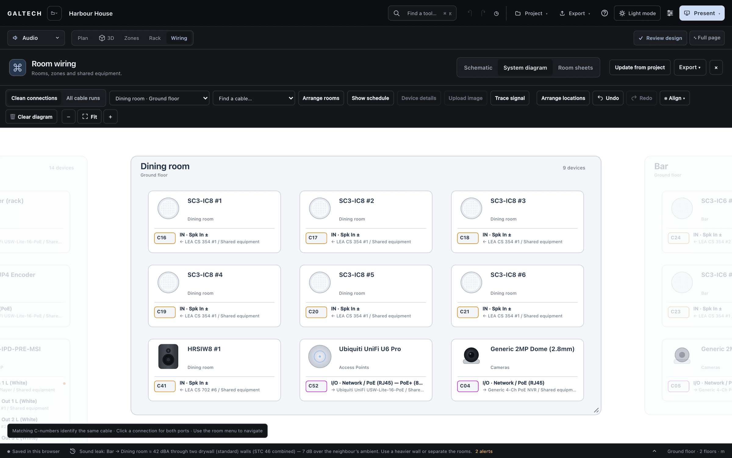
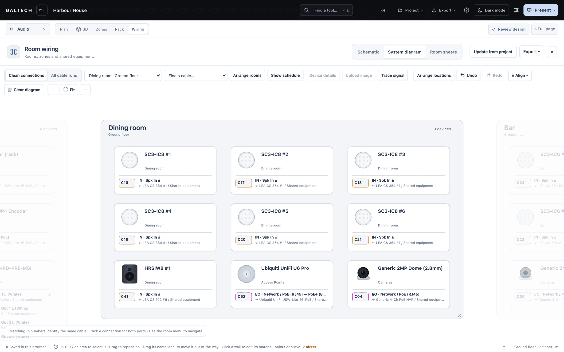
One set of connections, drawn three ways.
System diagram
The rack and the rooms as containers, each room a box with its receivers, screens, speakers, panels and cameras laid out inside, shown with real product photos and the cables as curves coloured by signal. The one for the client.
Schematic
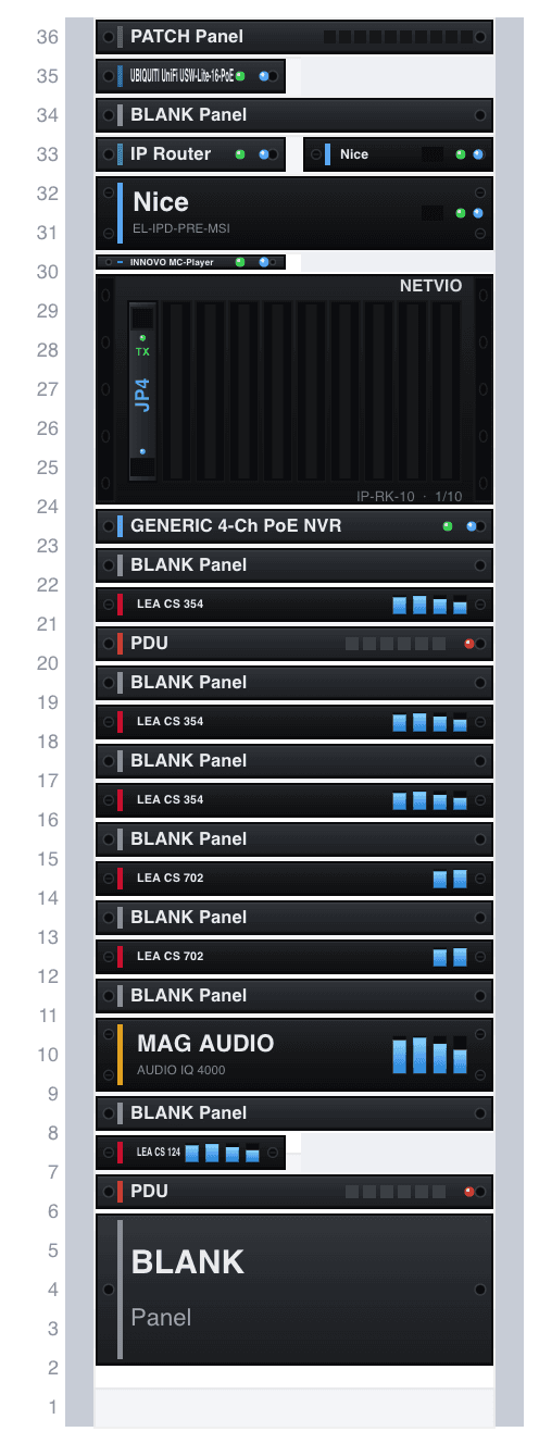
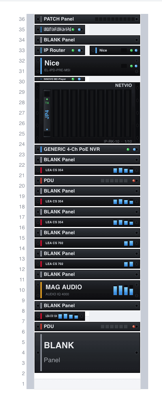
The port-level drawing: every device with its real rear connectors, cable IDs, and a cable schedule of each cable’s source, destination and type. The one for the installer.
Room sheets
One printed page per area, so the people pulling cable have their room’s connections in hand.
how it works
Follow ports and cable IDs from the diagram to the schedule.
Read and export the wiringTask guide 13 · 3 min
Choose the appropriate view
Open Wiring above the canvas. Schematic shows port-level connections; System diagram shows the broader device relationships; Room sheets groups the installation by location.
Read the drawing and schedule together
In Schematic, choose Arrange locations, then use the zoom controls to inspect the connections. Show schedule lists each cable ID, source, destination and type beside the drawing.
Export the connection drawing
Open Export and choose Export CAD to download the wiring DXF and keep it with the cable schedule. Open the file in your CAD application, use Zoom Extents and inspect the complete drawing before sharing it.
Keep in mind
Wiring CAD and plan CAD are separate exports. Use the plan export when you need the building layout and its background.
Lesson 03 · 9:38Zones, rack, wiring, reports and handover
The whole lessonbuild from project
Drawn from the design, kept when you redraw.
Build from project draws every device as a block: amplifiers, the audio matrix or DSP, switches, controllers, AV over IP encoders and decoders, HDBaseT matrices, every speaker, and the access points and cameras, each wired to the network switch over PoE. On a first build it wires the obvious chain: sources to the matrix, the matrix to the amplifiers, each amplifier to the speakers in its zones, with 70 and 100 V lines daisy-chained.
Then you adjust. Drag from an output to a matching input to add a wire; the editor refuses output to output and mismatched signals. Wires route around the blocks, and you add bend points by dragging. Your blocks, names, positions and wiring are kept when you build again.
Each block lists its model’s rear connectors, matched to the datasheet: an LEA CS 168 has 8 analogue inputs and 8 speaker outputs, and an ELAN EL-SC-150 has 3 IR ports, RS-232, USB and audio. Cables are identified from their connectors and colour-coded in the legend and the schedule.
export
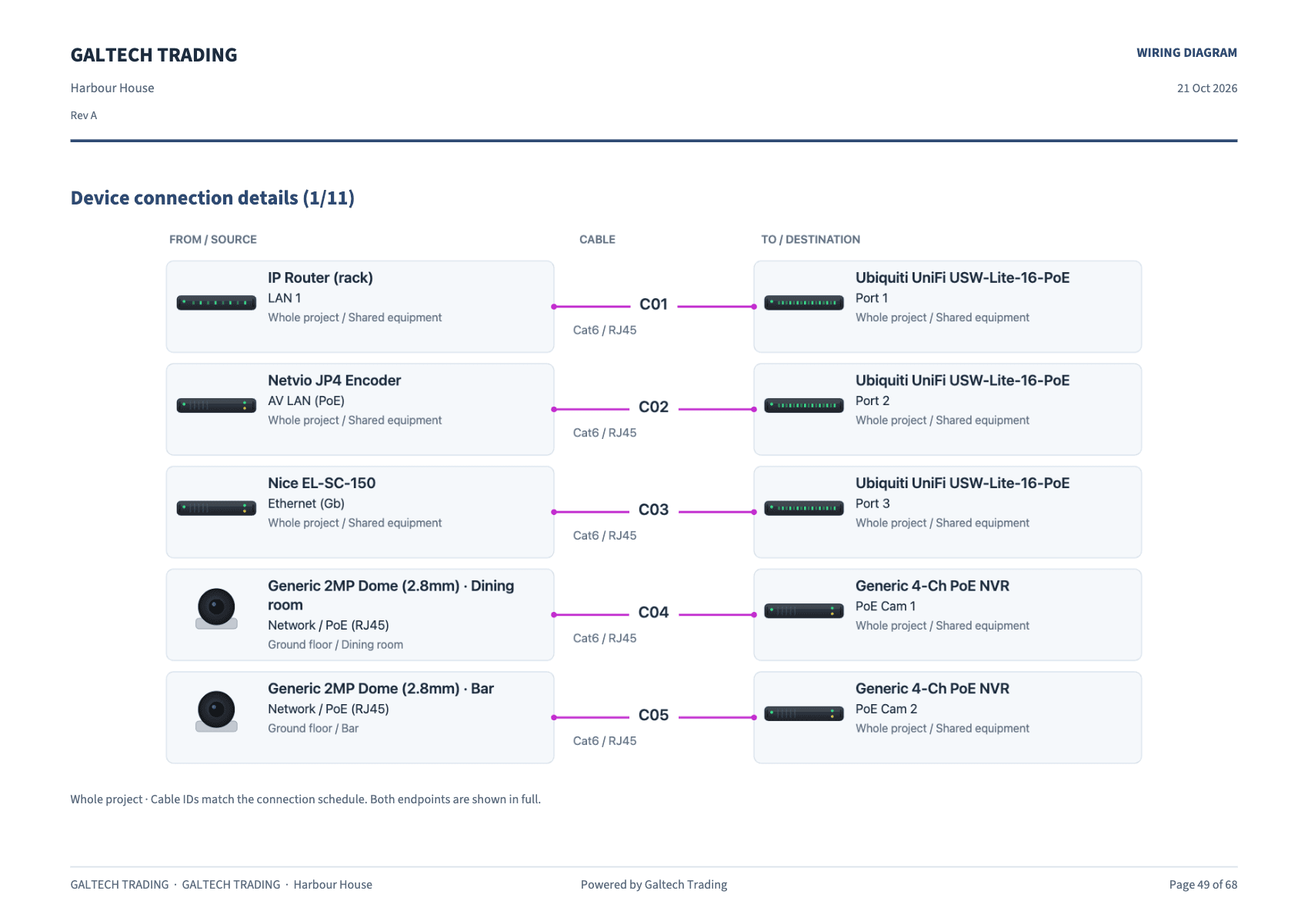
A drawing the installer can work from.
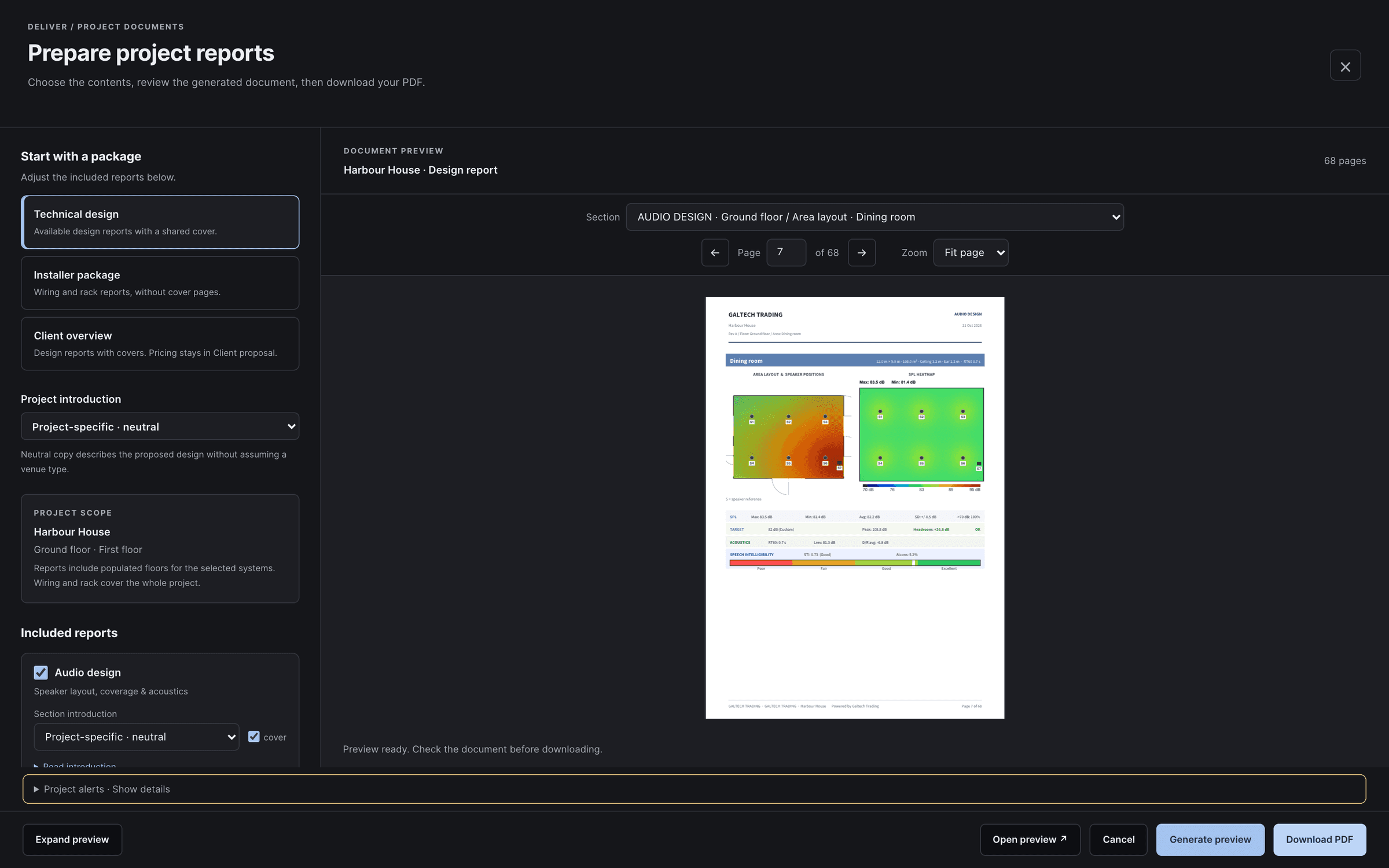
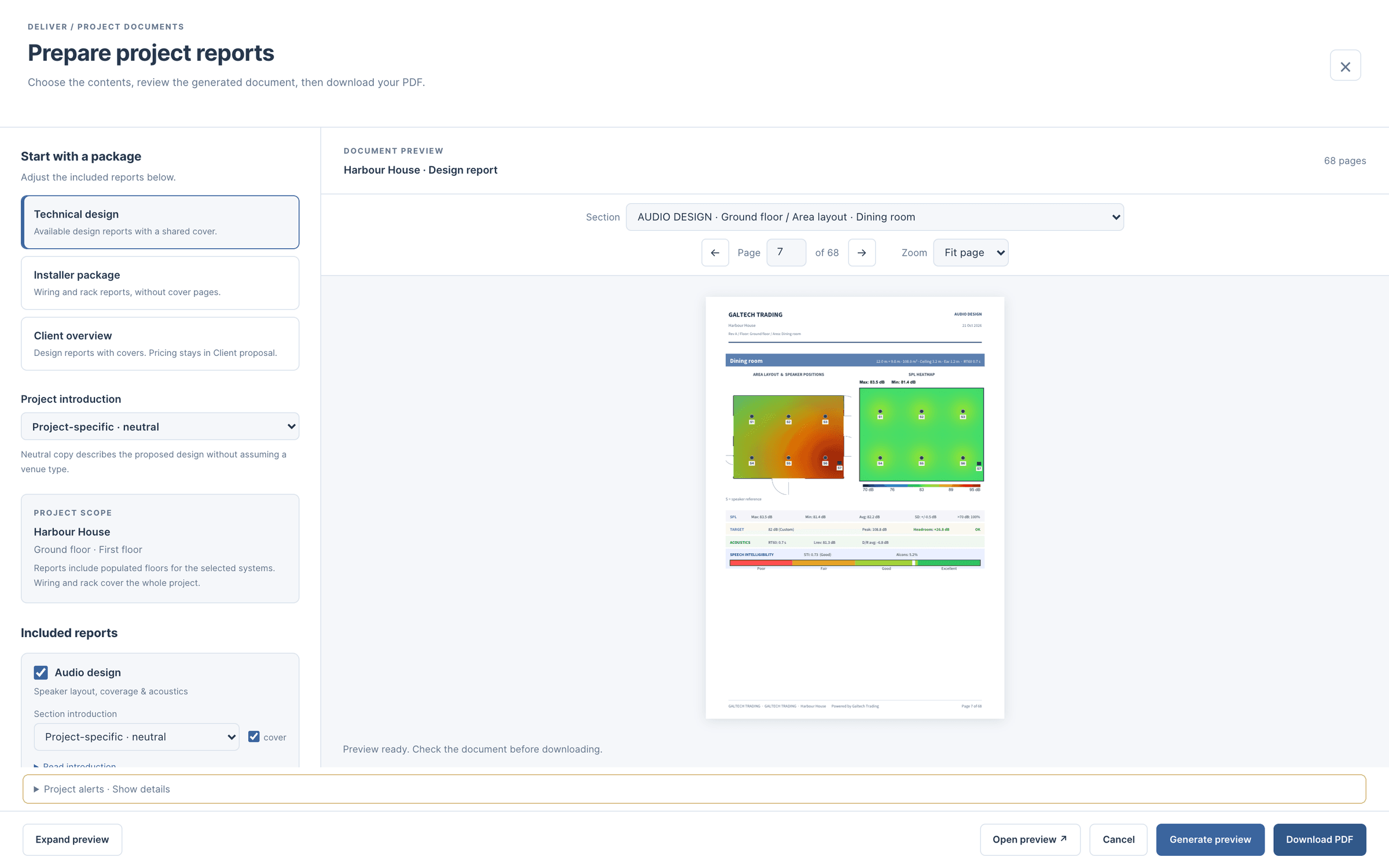
Export a PNG or a PDF of the view you are in. The PDF carries a title block with the project, the date and your branding, splits a large drawing across numbered sheets so the text stays readable, and ends with a numbered connection schedule: every from-port and to-port with its signal and cable type.
The wiring DXF carries the devices, the routes and a cable legend on their own layers. It is a separate export from the plan DXF, which carries the building and its background; keep the wiring DXF with the cable schedule.
review
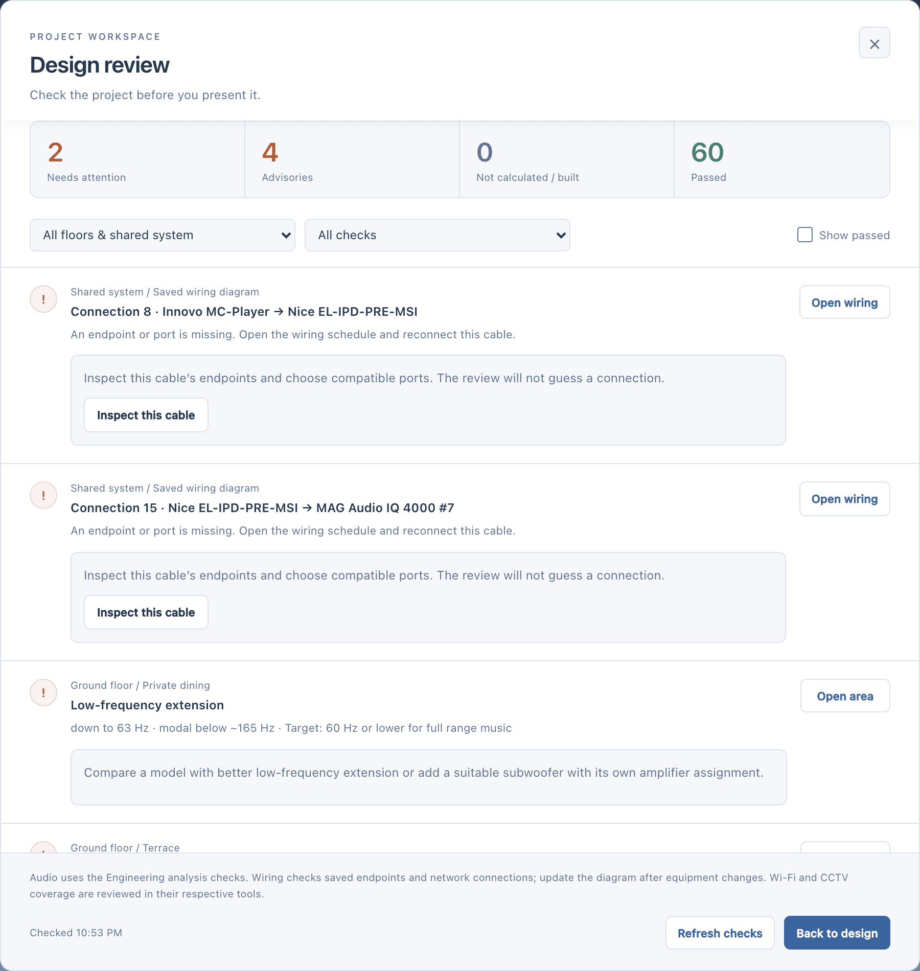
A missing port? Review design lists it.
Review design checks the saved wiring endpoints and network connections across the project. A connection whose endpoint or port is missing is listed with the reason and a button to inspect that cable. The review never guesses a connection for you.

in figures
Wiring, in figures.
- views: system diagram, schematic and room sheets
- 3
- export formats: PDF, PNG and DXF
- 3
- connection schedule, numbered, from-port to to-port
- 1
| Title block, numbered sheets and the connection schedule | |
| PNG | The view you are in |
| Wiring DXF | Devices, routes and a cable legend on their own layers |
| Room sheets | One page per area, for the installer |
| Cable types | Identified from the connectors: RCA, optical, coaxial, balanced, IR and more |
questions
Questions, answered plainly.
Is the wiring DXF the same as the plan DXF?
No. The wiring DXF is the connection drawing; the plan DXF is the building with its background. Export both when the installer needs the layout and the connections.
Will building the diagram again lose my edits?
No. Your blocks, renames, positions and wiring are kept when you build again; a rebuild never touches wiring you drew or edited.
Ready when the client is.
Draw it, check it, show it, price it and hand it over, from one project.
15-day trial for approved companies. No card, nothing to cancel.