Skip to content

For installers

Build what was designed, and check it on site.

Every cable has an ID, every rack unit has a place and every room has a sheet. Once the system is in, record what you measured beside what was predicted.

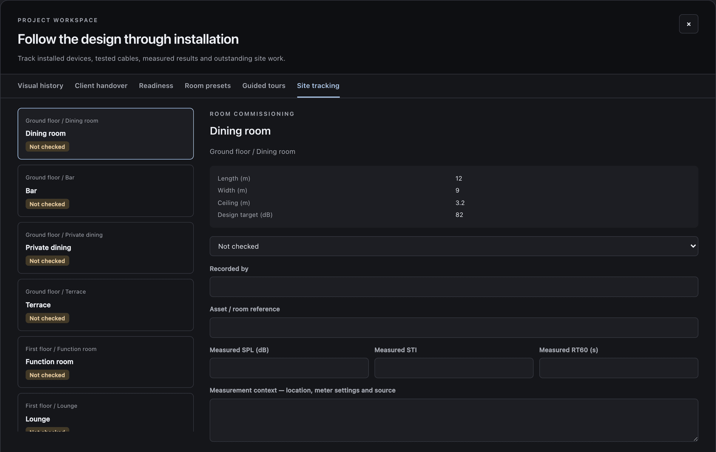
Site tracking in the dark theme, following the design through installation: the project’s six rooms, each not checked yet, and the dining room’s commissioning record, with its planned length, width, ceiling and 82 dB design target above a status, who recorded it, and empty fields for the measured SPL, STI and RT60 and the measurement context.
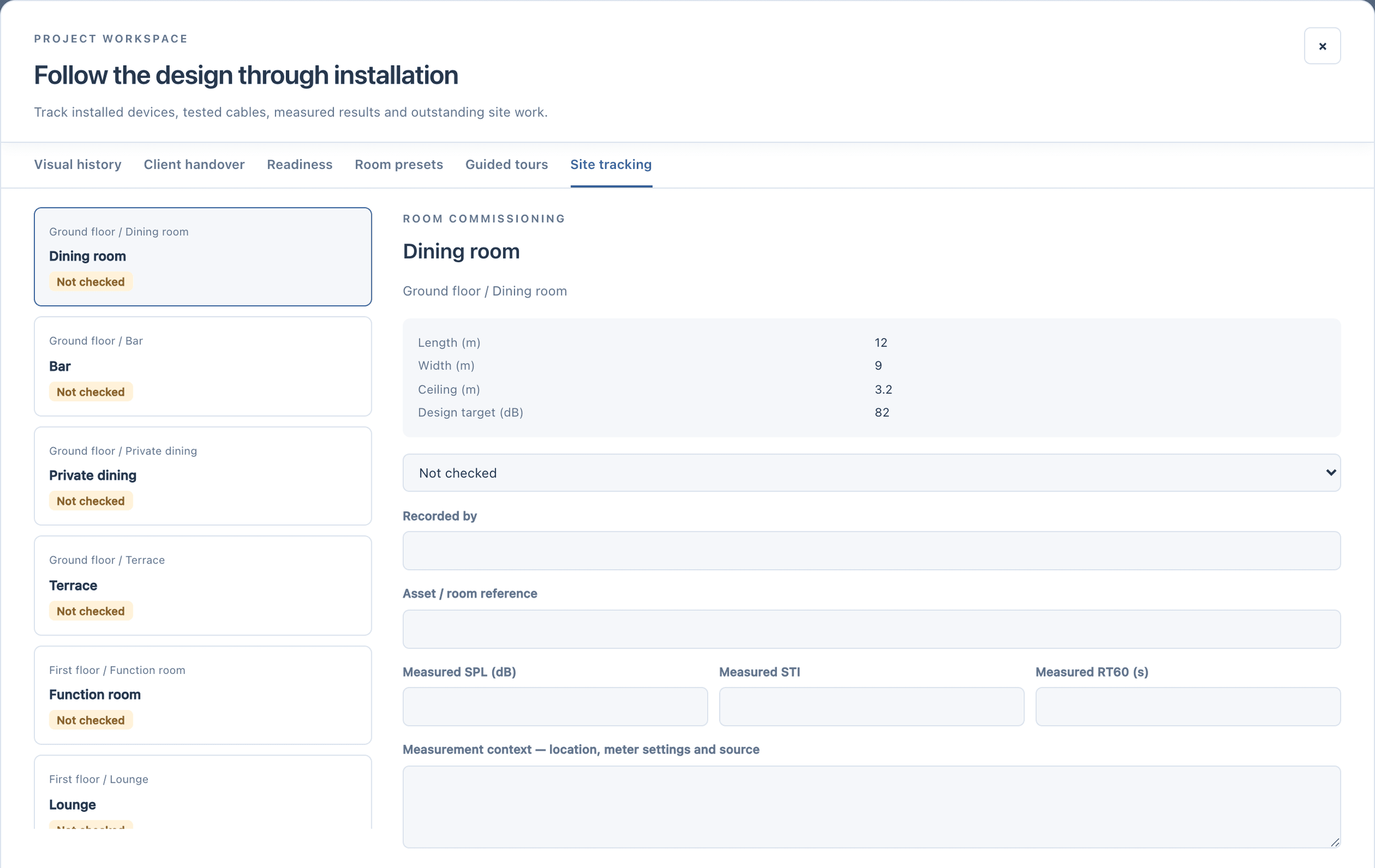
Site tracking, following the design through installation: the project’s six rooms, each not checked yet, and the dining room’s commissioning record, with its planned length, width, ceiling and 82 dB design target above a status, who recorded it, and empty fields for the measured SPL, STI and RT60 and the measurement context.
Site tracking on the demo project: each room’s commissioning record, with the design target above the fields for what you measure.

the job

Hand-drawn schedules, and nothing on site to check against.

Build what was designed, and check it on site. The schedules, the rack and the drawings come from the same project the client signed.

Where the time goes

  • Schedules drawn up by hand, apart from the drawing they describe.
  • Cables that are hard to find again once they are in the wall.
  • Nothing on site to check the finished system against.

What changes

  • The cable schedule comes from the drawing: every cable has an ID, a source port, a destination port and a type.
  • The IDs print on the report and the room sheets, so both ends can be labelled before the cable goes in.
  • Site tracking keeps the measured SPL, STI and RT60 per area beside the prediction.

on site, 06

First fix to handover, from one project.

  1. Before first fix

    Room sheets and the cable pull

    Room sheets print one page per area. The BOM file adds a speaker schedule with mount, height, position and aim, and a pull schedule per run: the length from the plan, the ceiling drop and 15% slack.

  2. Rack

    Build the rack from its elevation

    Front and rear views with the PDU outlets, the power draw, the current with 25% headroom and the breaker it needs, the heat in BTU/h and the weight. Export it as PDF, DXF or PNG.

  3. Network

    Addresses before the first boot

    The same file lists every amplifier, AV-over-IP and control device with a suggested IP address, VLAN and audio-network role, ready for the site IT team.

  4. Commissioning

    Load the DSP preset, then measure

    The DSP preset sheet gives every output its level, polarity, filters, crossover, EQ, limiter and delay, with a calibration walk sheet per speaker. Verify with an SPL meter, and an STI check for speech.

  5. As built

    Calibrate the model to the room

    Type the measured average SPL into the area’s site calibration, and the heatmap, the levels and the standards check shift to match. Calibrated areas print a predicted against measured table in the audio report.

  6. Handover

    Record what was installed and tested

    Site tracking gives every device and cable a status, from not checked to verified or needs attention, with who checked it and when. A design change flags finished items for a recheck.

the drawings

Three views of the wiring, and the rack it all lands in.

Wiring in three views

The system diagram shows the rack and the rooms as containers, for the client. The schematic goes port by port, with cable IDs and a cable schedule. Room sheets print one page per area for the installer.

  • Drag from an output port to a matching input to add a wire; mismatched signals are blocked.
  • Audio runs are labelled RCA, optical, coaxial or balanced, and IR is its own cable.
  • The PDF carries a title block and ends with a numbered connection schedule.
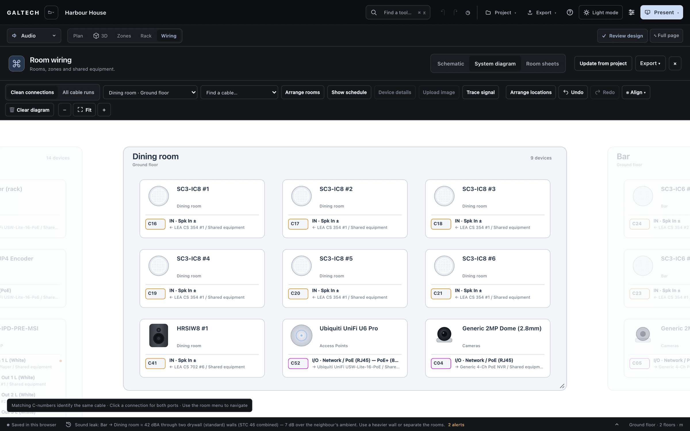
Room wiring as a system diagram in the dark theme: the dining room container on the tool’s light diagram with six SC3-IC8 speakers, an HRSIW8 subwoofer, a UniFi U6 Pro and a dome camera, each tagged with its cable ID and the port it connects to.
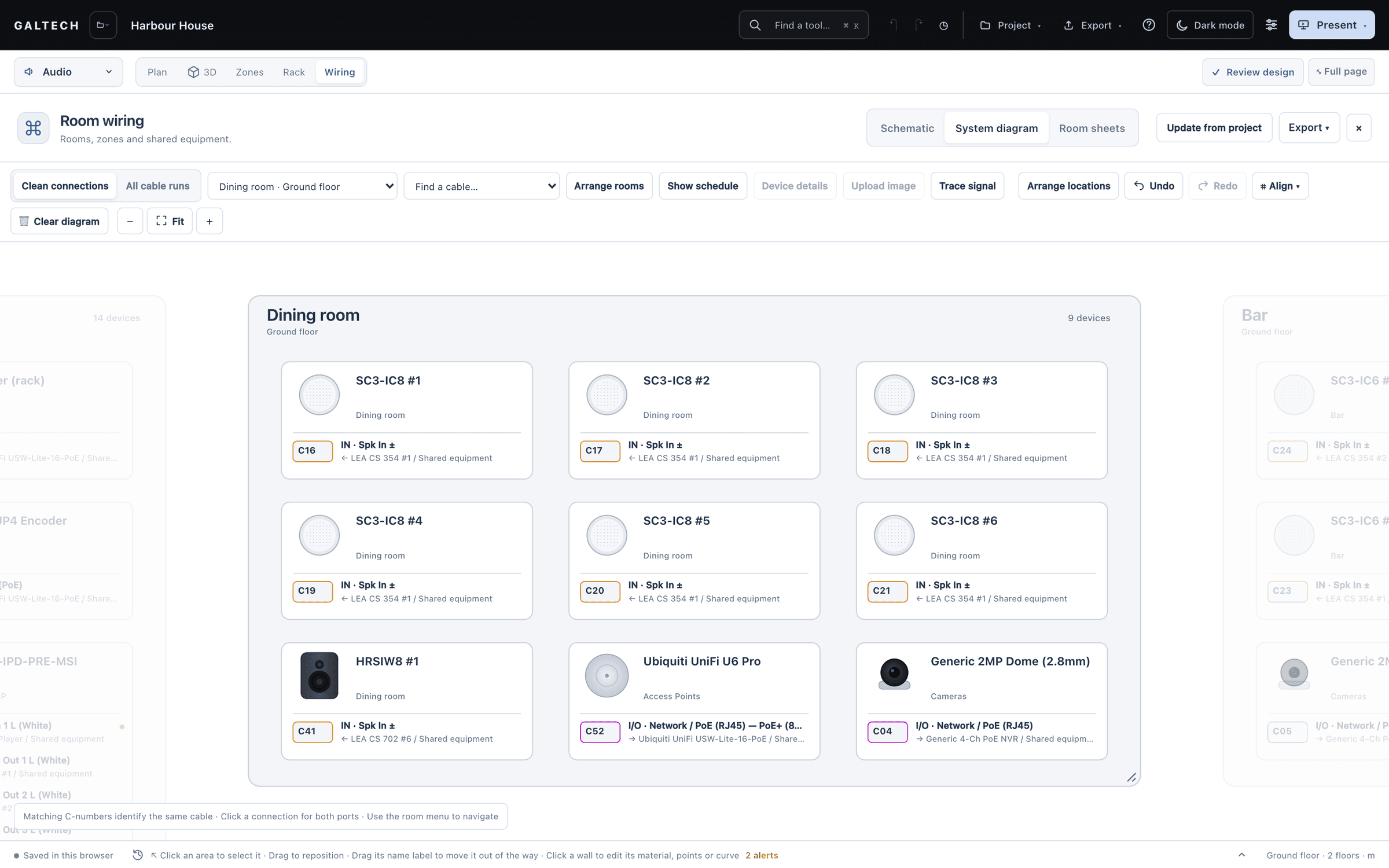
Room wiring as a system diagram: the dining room container with six SC3-IC8 speakers, an HRSIW8 subwoofer, a UniFi U6 Pro and a dome camera, each tagged with its cable ID and the port it connects to.
The system diagram on the demo project: each device tagged with its cable ID and the port it connects to.

The rack, before it is built

Auto-fill lays the cabinet out from the top: patch panels, the network switch, the controllers and the rest of the gear, then the amplifiers with a blank above each row and PDUs sized to the mains-powered gear. The cabinet is resized to fit.

  • Front and rear views, with each unit’s power cable routed to a PDU outlet.
  • The power budget at 230 or 120 V: the draw, the current with 25% headroom, the breaker, the heat and the weight.
  • Your own front-panel photo on any unit, when the elevation should match the real rack.
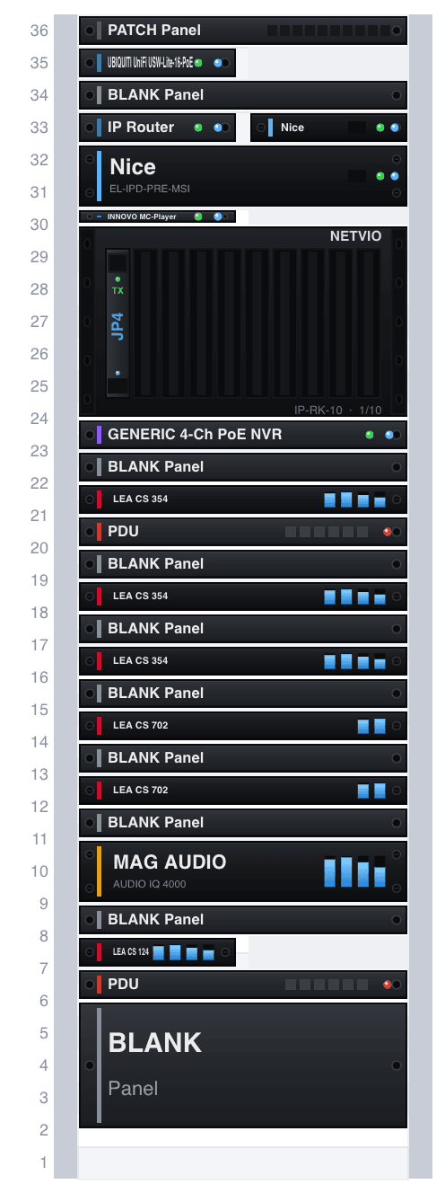
A 36U rack elevation: patch panel, UniFi switch, IP router, Nice processor, Innovo player, a Netvio chassis with a JP4 encoder, a 4-channel PoE NVR, LEA and MAG Audio amplifiers, PDUs and blanking plates, on the tool’s white rack drawing.
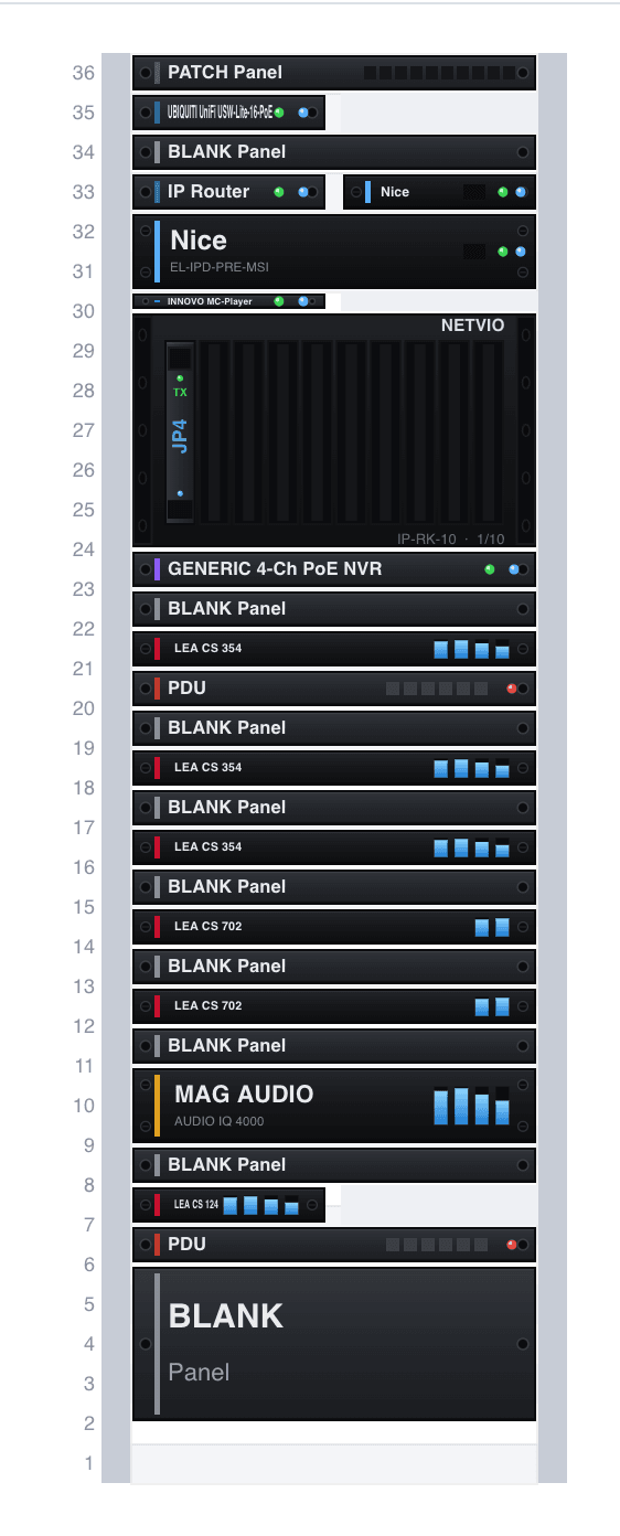
A 36U rack elevation: patch panel, UniFi switch, IP router, Nice processor, Innovo player, a Netvio chassis with a JP4 encoder, a 4-channel PoE NVR, LEA and MAG Audio amplifiers, PDUs and blanking plates.
A 36U elevation from the demo project, from the patch panel at the top to the amplifiers and PDUs.

what you take to site, 08

Drawings, schedules and the record you leave behind.

  • For the client

    • Client handover

      A PDF, or a ZIP with the drawings and the equipment, cable and commissioning schedules.

      • PDF
      • ZIP
  • For the installer

    • Wiring drawings

      The system diagram for the client, and the port-level schematic with a numbered connection schedule.

      • PDF
      • PNG
    • Room sheets

      One page per area, with its equipment and connections, for the people pulling the cable.

      • PDF
    • Rack elevation

      Front and rear, with the PDU outlets, the power budget, heat and weight.

      • PDF
      • DXF
      • PNG
    • CAD drawings

      The plan over its original underlay, a 3D model of the rooms, and the wiring with cable layers.

      • DXF
    • DSP preset sheet

      Level, polarity, filters, crossover, EQ, limiter and delay for every output, with a calibration walk sheet.

      • PDF
    • Commissioning record

      Every device and cable with its status, and the measured SPL, STI and RT60 per area.

      • CSV
  • For the office

    • Priced bill of materials

      The BOM with the speaker installation schedule, the cable schedule and a pull schedule per run.

      • CSV

pricing

Your company’s subscription, or your dealer’s account.

On a dealer’s team? The tools are in the dealer’s portal. Every other company starts with a 15-day trial.

For companies trying it on a real job

Trial

15 days

  • No card
  • Nothing to cancel

Request access, we approve your company, and the trial starts with a set-up link by email.

  • The full workspace and all five disciplines
  • Premium tools: amplifiers, zones and the client proposal
  • Reports, BOM, DXF and Share 3D
  • The Windows app and cloud projects
  • For approved companies
  • Adding your own products is not part of the trial

For integrators and installers

Professional

AED 7,500per year

≈ USD 2,042, billed in AED

  • Per company
  • Excl. 5% VAT
  • Invoiced annually
  • Billed in AED

Every discipline and every output, for the whole company, on one annual invoice.

  • Audio, Wi-Fi, CCTV, video and control on one plan
  • The full catalogue of 308 devices
  • SPL, STI and RT60, with the Ray-Traced Check (beta)
  • 3D presentation, walk and listen, and Share 3D by QR
  • Branded reports and a priced client proposal
  • BOM and quote lines as CSV, drawings as DXF
  • Rack, wiring, DSP preset sheet and site tracking
  • Windows app with 7 days offline, cloud projects and 25 backups
  • Your own products and price lists, switched on per account on request

questions

Asked plainly, answered plainly.

Can I open the drawings in my CAD software?

Yes. The plan, the 3D model, the wiring and the rack export as DXF. A plan over a PDF or image comes as a ZIP with the DXF and its background: keep them in one folder.

Does site tracking pass or fail a room?

No. It keeps the measured SPL, STI and RT60 beside the design values as a record. To make the model match the room, use site calibration, which trims the prediction by the difference you measured.

How close will my meter be to the prediction?

The tool’s help says where the model is strongest and where to treat it as an estimate. Predictions are a planning baseline, not a guarantee: commission with an SPL meter, and an STI check for speech.

Prediction accuracy
Do I need a connection on site?

Not with the Windows app, which works offline for up to 7 days at a time and syncs when you reconnect. The web app needs a connection. Room sheets and schedules also print.

Windows app

Every cable numbered before the first one is pulled.

Try it on a real job: approved companies get a 15-day trial.

15-day trial for approved companies. No card, nothing to cancel.

Search the site