Design
One plan, shared by all five disciplines.
Start from the architect’s drawing, at the right scale. Import the architect’s PDF, image, DXF or DWG, set the scale from one distance you know, then trace the rooms. Audio, Wi-Fi, CCTV, video and control all read the same walls.
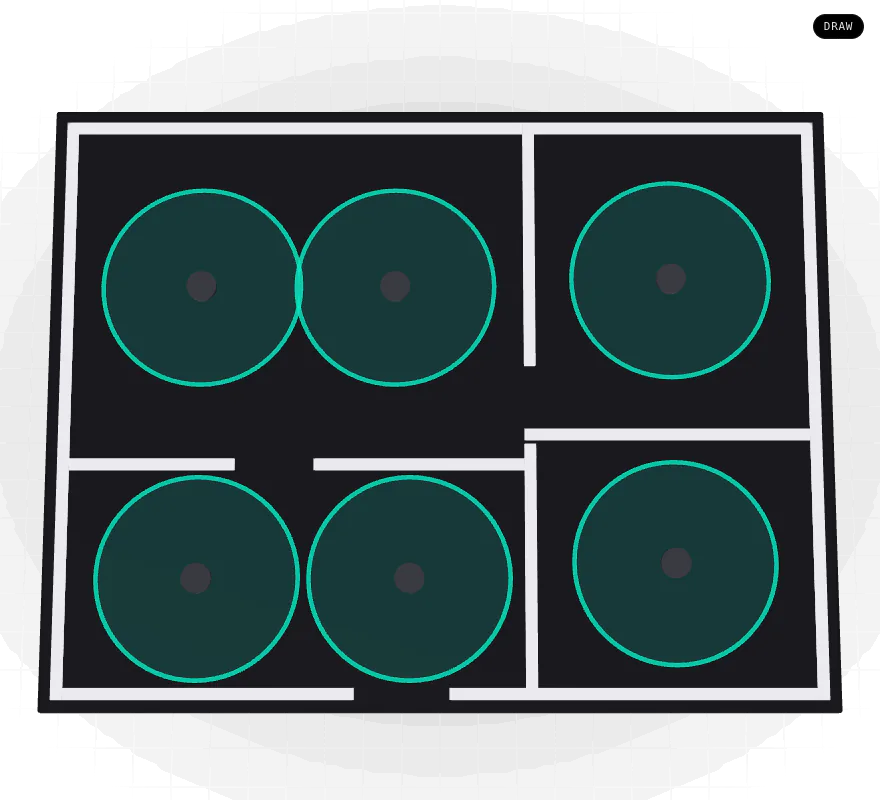
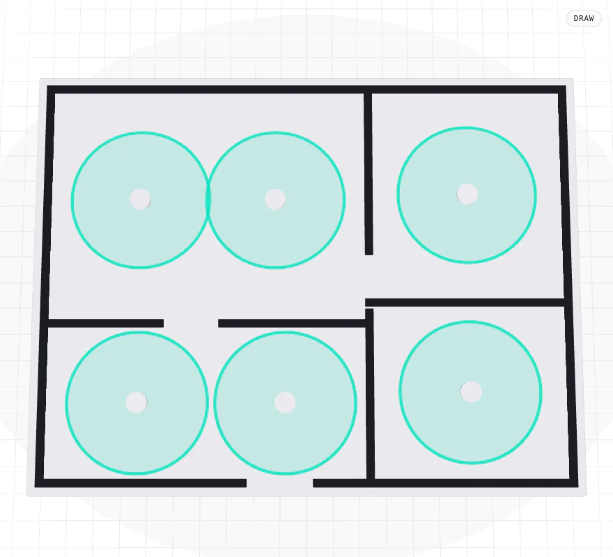
import
Any drawing the architect sends, opened as it is.
Import the plan from the Project explorer. PDF, PNG and JPG plans open directly, and so do CAD files: a DWG is converted to DXF inside the browser by a converter that downloads once (about 10 MB). Any ASCII DXF version imports, from R12 to the latest. A binary DXF still needs converting first, with the free ODA File Converter or Save As in AutoCAD.
Architect files are often hundreds of megabytes. The tool streams them and keeps only the wall and room-label layers, so even a 350 MB plan opens in a couple of seconds, and the file never leaves your computer.
Pick your drawing
When a CAD sheet holds several drawings side by side, the tool shows a thumbnail of each and marks the most plan-like one. Click your floor plan; the rest are set aside.
Crop to the plan
Or box the plan yourself with Draw, Crop to plan. Room detection then works inside that box, and you can crop again at any time.
Choose the CAD layers
Tick the layers that are walls, partitions, doors and glazing, and the one that holds the room names. A missing wall layer is the usual reason a room will not detect.
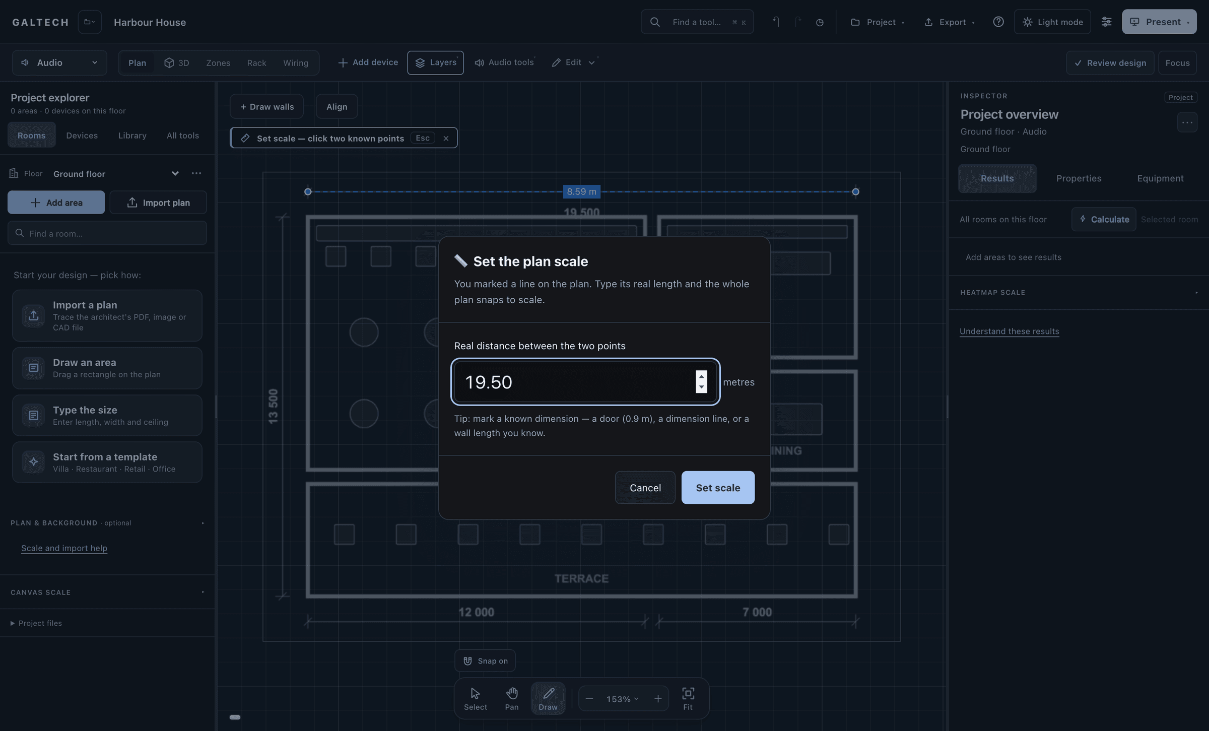
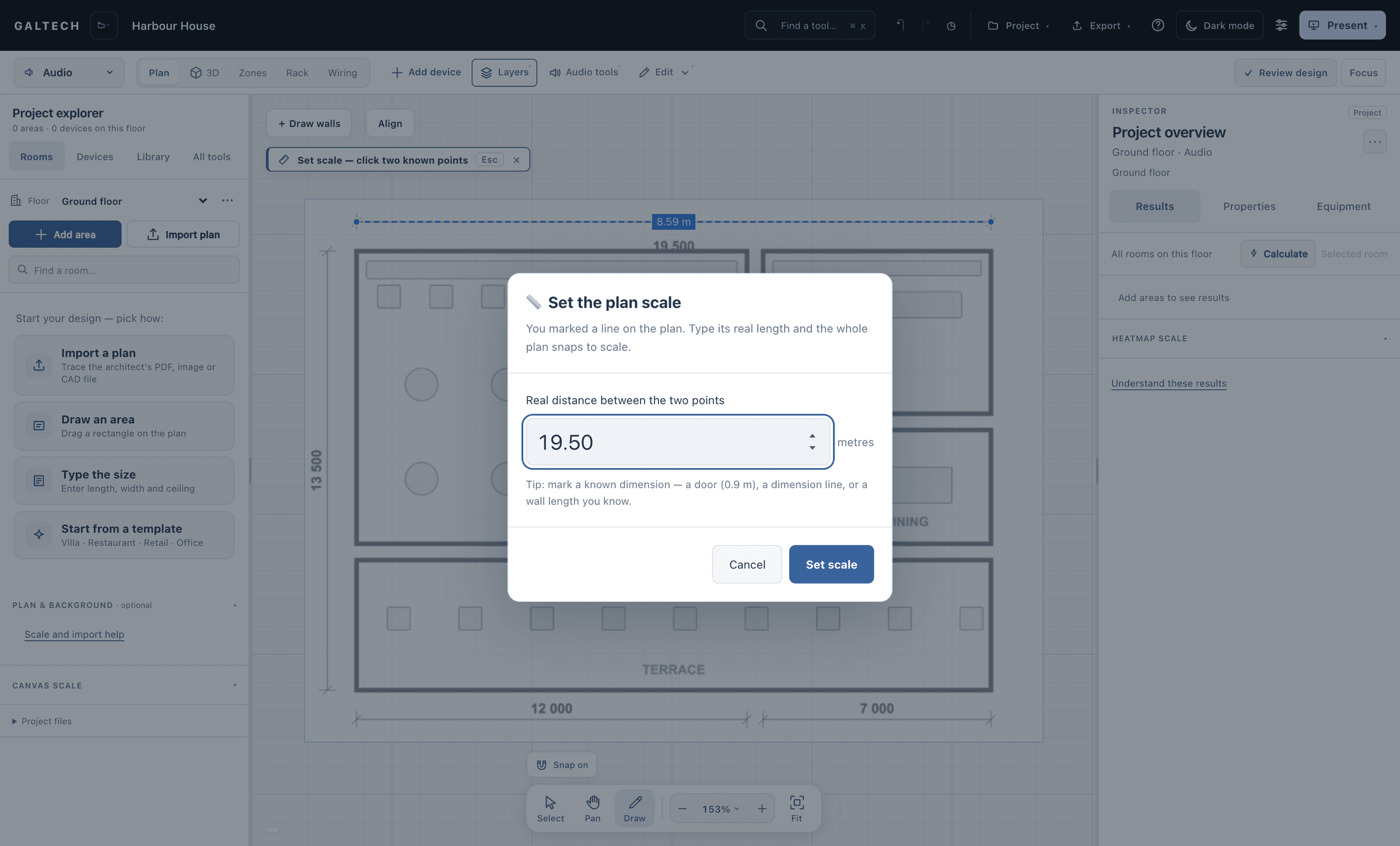
scale
Set the scale once, then check it twice.
A PDF or an image carries no real-world size. Open Draw, Set scale, click both ends of a distance you know (a 0.9 m door, a printed dimension line, a wall) and type its real length in metres. The whole plan snaps to scale and stays exactly where it is on screen.
Before you trace, mark a second known dimension and read the distance the tool suggests, without applying it. If it agrees with the drawing, the scale is right. Coverage, cable lengths and every schedule depend on it, so this is the minute that saves the job.
A DXF carries its own scale, so the step is mainly for PDF and image plans, though it corrects any plan.
Each floor has its own plan
Select the floor in the Project explorer before you trace: every floor keeps its own background and layout. Keep the background where it is once tracing starts.
how it works
From the drawing to traced rooms, in six steps.
The two task guides the Learning Centre gives for this, as the tool words them.
Import and scale a floor planTask guide 02 · 3 min
Import the drawing
In the Project explorer, choose Import plan and select the floor plan. For a multipage PDF, choose the page containing the floor you need.
Calibrate a known distance
Open Draw on the canvas dock and choose Set scale (calibrate). Click both ends of a labelled distance on the drawing. Enter its actual length in metres, then choose Set scale. The example uses the 10.00 m dimension.
Trace on the correct floor
Select the floor in the Project explorer, then add its areas and devices. Each floor has its own background and layout. Keep background alignment consistent after you start tracing.
Keep in mind
Verify a second dimension before tracing. Use Set scale (calibrate) to mark its endpoints and check the suggested distance. In this example, the 6.00 m dimension should read 6.00 metres. Choose Cancel to finish this check without applying another scale. Device coverage and cable estimates depend on the correct scale.
Draw and edit individual wallsTask guide 03 · 3 min
Select and resize a wall
With Select active, click the middle of a wall segment. The blue highlight, end handles and wall number in Edit wall identify your selection. Change Length, then press Tab or click outside the field to apply it. Inspect the adjoining corners after the change.
Choose its material
Select the intended segment, open Wall material and choose the construction type. Scroll the material list if needed. Check the highlighted choice, then select another wall to inspect its own setting. Material and wall shape are separate choices.
Curve or straighten the wall
Choose Arc to expose the Bend field. Adjust Bend in small steps, pressing Tab or clicking outside the field to apply each value. Review the curve and its endpoints in the plan. Choose Straight to remove the bend.
Keep in mind
Start a new outline with Draw or Draw walls, then refine its individual segments. Length changes can alter adjoining corners. Check the complete outline, its alignment with the reference plan, and the intended construction material before continuing.
Lesson 01 · 12:49The workspace, floors and plans
- 6:42Add an area
- 7:29The Draw menu
- 8:06Import and scale a plan
- 9:07Draw walls and materials
- 9:33Edit one wall
- 10:09Floors
rooms
Rooms by detection, by a click or by hand.
Three ways to turn a drawing into design areas, from the fastest to the most controlled, and a fourth for CAD plans.
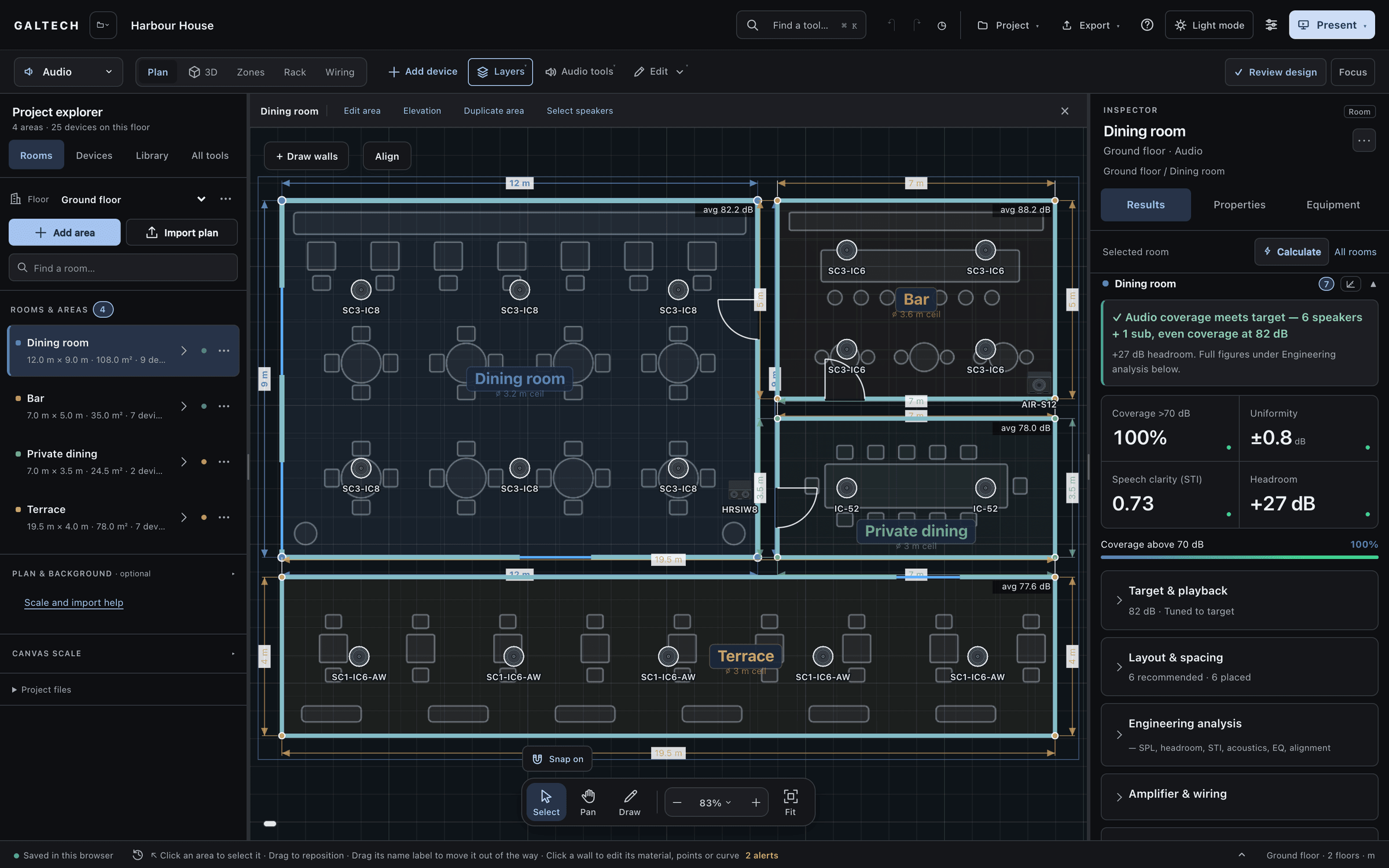
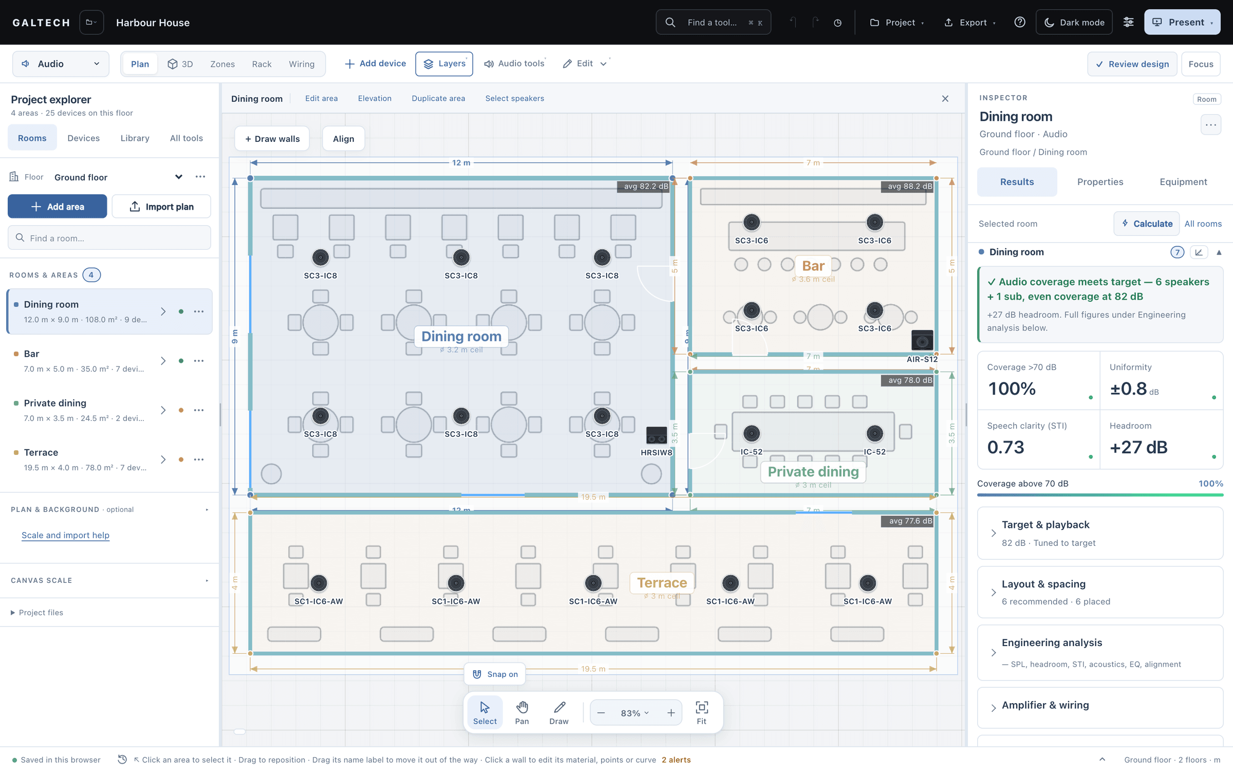
Detect all rooms
Finds every enclosed room at once, adds each one to scale and, on a DXF, names it from the CAD label inside. Delete the ones you do not need. An open-plan floor with no interior walls stays one area.
Fill room
Click inside a room and it floods out to the walls, traces the outline and names it. A rectangle comes out as a clean rectangle, an L-shape as a polygon. If the fill escapes through an open doorway, the tool says so.
Trace
Draw walls corner by corner over the plan. A live ruler shows every length, lines snap square and to 45°, and you can type a length, Tab for the angle and Enter to place it. Drag sideways while placing a point to bow the wall into an arc.
Click to place, on a DXF
Pick a speaker, access point or camera and click inside a room: the tool reads the CAD walls around the click and creates that room on the spot, named from its label.
Rows of identical rooms
Rooms drawn side by side snap onto the same wall line, with no overlap. Select an area and press Ctrl or ⌘ and D to duplicate it with its speaker layout, for a row of hotel rooms, offices or retail units.
walls and materials
Every wall has a length, a shape and a material.
With Select, click a wall segment to edit it on its own. Set its length, add a point for a recess, turn it into an arc with a bend value, or delete it. The corners and the neighbouring walls follow, and the room outline stays closed.
The material is a separate choice, and every module reads it. Wi-Fi takes the radio loss through the wall. Audio takes its sound isolation (STC), which sets how much spills into the next room. 3D draws the wall in that material.
Doors go on any wall as an opening, a glass door or a window on a sill. Interior partitions and round walls (bar counters, columns, planters) block sound, and open sides or an open sky turn an area into a terrace or a garden.
| Material | Wi-Fi loss at 5 GHz | Sound isolation |
|---|---|---|
| Walls | ||
| Drywall, standard | 3 dB | STC 34 |
| Drywall, heavy duty | 4 dB | STC 45 |
| Brick | 5 dB | STC 45 |
| Wood | 5 dB | STC 30 |
| Metal | 10 dB | STC 25 |
| Concrete | 15 dB | STC 50 |
| Glass | ||
| Glass, standard | 2 dB | STC 30 |
| Glass, thin | 1 dB | STC 26 |
| Doors | ||
| Door, wood | 5 dB | STC 25 |
| Door, metal | 10 dB | STC 30 |
| Door, glass | 2 dB | STC 26 |
| Windows | ||
| Window, single pane | 4 dB | STC 27 |
| Window, double pane | 7 dB | STC 35 |
| Window, triple pane | 10 dB | STC 40 |
floors and templates
Several floors, metres or feet, and a head start.
A project holds as many floors as the building needs, each with its own plan, areas and devices, while the rack, the zones and the wiring serve the whole building. In 3D you see the floor you have selected. Work in metres or in feet.
To start faster, 14 venue presets fill in an area’s target level, reverberation, noise floor and speaker spacing and suggest a speaker, and 4 project templates (a villa, a restaurant, a retail unit and an office) open a complete starting point: areas, speakers laid out by the advisor, Wi-Fi and CCTV, already calculated.
in figures
The numbers behind the plan.
- plan formats: PDF, image, DXF and DWG
- 4
- wall materials, each with its radio loss and its STC
- 14
- venue presets
- 14
- project templates
- 4
| Plans in | PDF, PNG, JPG, DXF (R12 to the latest, ASCII) and DWG |
|---|---|
| Scale | Two points and a known length, in metresA DXF carries its own scale |
| Rooms | Detect all rooms, Fill room, trace, or click to place on a DXF |
| Walls | Length, added points, arcs and a material per segment |
| Openings | Doors, glass doors, windows, open sides and open sky |
| Floors | As many as the building needs; 3D shows the selected floor |
| Units | Metric or imperial |
| Plan out | DXF with the PDF or image background as a referenced underlay, in a ZIP |
questions
Questions, answered plainly.
Can I import a DWG directly?
Yes. The tool converts a DWG to DXF in the browser; the converter downloads once, about 10 MB. If an unusual DWG fails, convert it to an ASCII DXF with the free ODA File Converter or Save As in AutoCAD, and import that.
Does a PDF plan come in to scale?
No. A PDF, PNG or JPG carries no real-world size. Set the scale from a known distance, then check a second dimension before you trace. A DXF carries its own scale.
My plan dimensions are wrongCan I design without a plan?
Yes. Add areas from a form with their length, width, ceiling height and ear level, or draw them by hand, and import a plan later if one arrives.
Does the plan go back out with the design?
Yes. The plan DXF export keeps a PDF or image background as a referenced underlay: it downloads as a ZIP with the DXF and the background files, which you keep in one folder. A CAD plan is redrawn with your design on it, on its own layer.
Ready when the client is.
Draw it, check it, show it, price it and hand it over, from one project.
15-day trial for approved companies. No card, nothing to cancel.