Review and delivery
Export CAD drawings
Export the floor plan, the 3D model, the wiring and the rack as DXF, keep a PDF or image background with the drawing, and open the files in AutoCAD and others.
On this page
The design exports to CAD four ways, and they are different drawings for different people. Send the plan to the architect or the site manager, the wiring to the installer, and keep each with the documents it belongs to.
| Export | Where | What it holds |
|---|---|---|
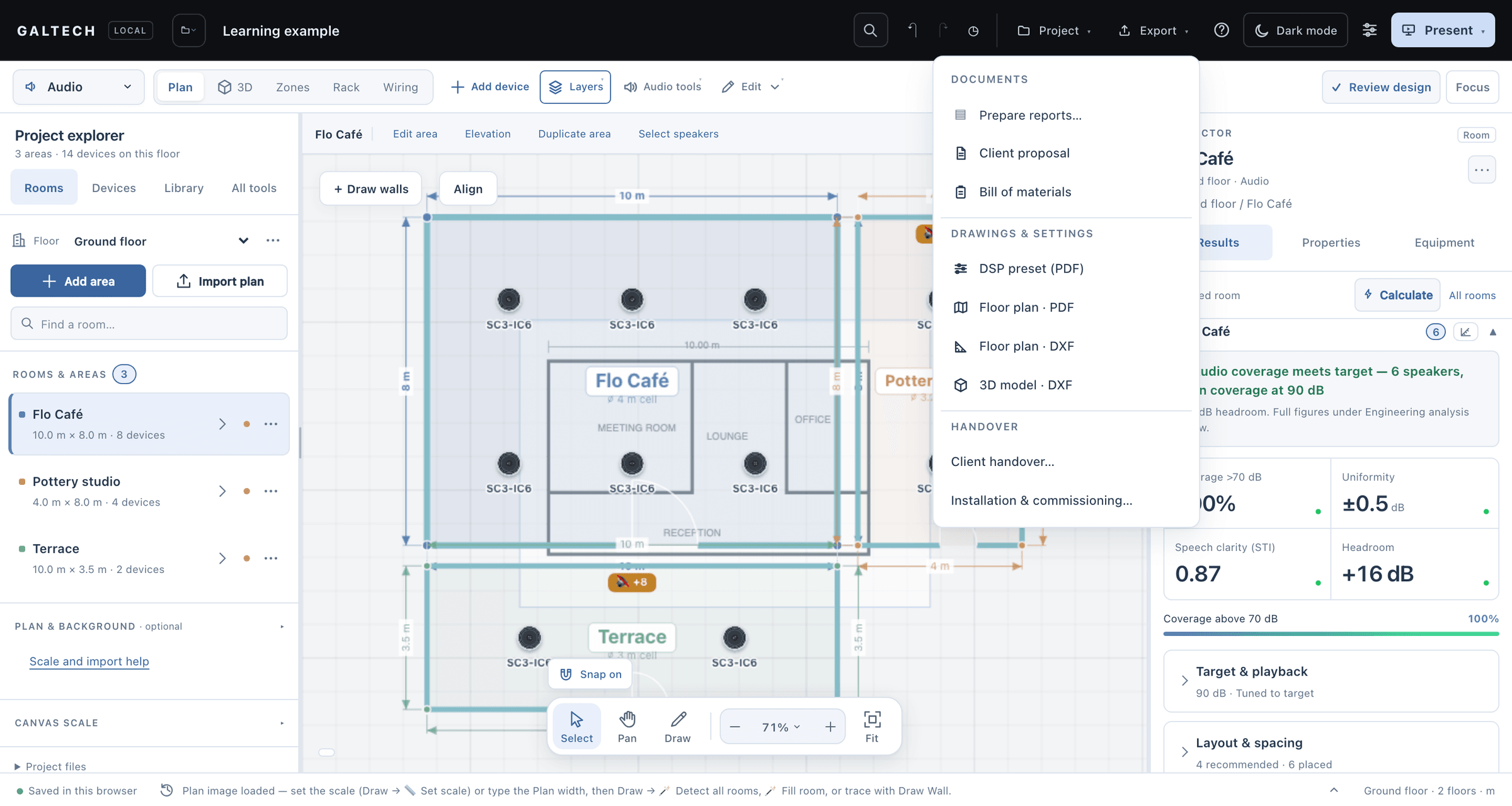
| Floor plan · DXF | The Export menu | The building plan: areas, walls, device positions and the plan background |
| 3D model · DXF | The Export menu | The rooms as solids and every device as a box at its mounting height |
| Wiring DXF | Wiring → Export | The connection diagram: devices, routes and a cable legend |
| Rack DXF | The Rack Designer | The rack elevation, at real scale |
Export the floor plan with its background
- Open Export and choose Floor plan · DXF. Use it for the building plan; use the wiring export for the connection diagram.
- If the plan has a PDF or image background, the download is a ZIP holding the DXF and the background images. Extract every file into the same folder.
- Keep the background files beside the DXF, so AutoCAD can find them. Open the DXF and use Zoom Extents to see the whole drawing.
- When you share the plan, send the whole extracted folder.
Note
A native CAD background stays as editable vectors where the format allows. A PDF or image background is exported as a referenced image, which is why it travels as separate files.
What is in the plan DXF
- Everything at true size. A round in-ceiling speaker is a circle at its real cut-out diameter. A flat or invisible panel is a rectangle at its real cut-out, turned the way you placed it, so nobody cuts a round hole for a square speaker. Anything that fires forward gets an aim line.
- Access points and cameras, each on its own layer, with a label.
- Dimensions and a title block: each area’s size, each device’s distance to the walls, and the project details.
- A legend beside the drawing that names every model used, its mount and shape, and how many there are, with the symbol the plan uses.
- Layers per floor. A multi-floor job exports every floor, side by side and labelled, each on its own layers, such as
AREAS_GROUND-FLOORandSPEAKERS_FIRST-FLOOR. - The architect’s drawing. If you imported a DXF, it comes back on its own
CAD_PLANlayer, which you can freeze. The architect’s own walls are always kept.
The 3D model
3D model · DXF turns each area into solid geometry, the floor and the walls up to the ceiling height, and drops every device in as a box at its real mounting height: speakers by mount, access points on the ceiling and cameras at their set height. Devices sit on layers you can freeze. A multi-floor job is stacked at the floors’ real heights. It opens in SketchUp, AutoCAD, BricsCAD and LibreCAD.
The wiring and the rack
- Wiring. In the Wiring view, open Export and choose Export CAD. The DXF holds the devices, the routes and a cable legend on layers. Open it in your CAD application, use Zoom Extents and check the whole drawing before you share it. See Read and export the wiring.
- Rack. The Rack Designer exports a real-scale DXF of the elevation, beside its PDF and PNG. See Build the equipment rack.
A one-page PDF of the plan
Floor plan · PDF, in the same menu, prints the 2D design over your imported background on one page: the areas, the placed devices and the room names, with the heatmap if that layer is on.