Systems
Design Wi-Fi coverage
Place access points on the shared plan, read the predicted signal per band through walls of real materials, auto-place to a coverage target, check the ports.
On this page
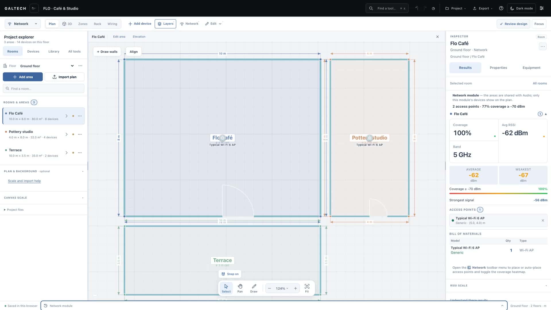
Switch the discipline selector to Network. The rooms are already there, because every discipline shares the plan: you place access points, and the tool predicts the signal in every room through the walls you drew.
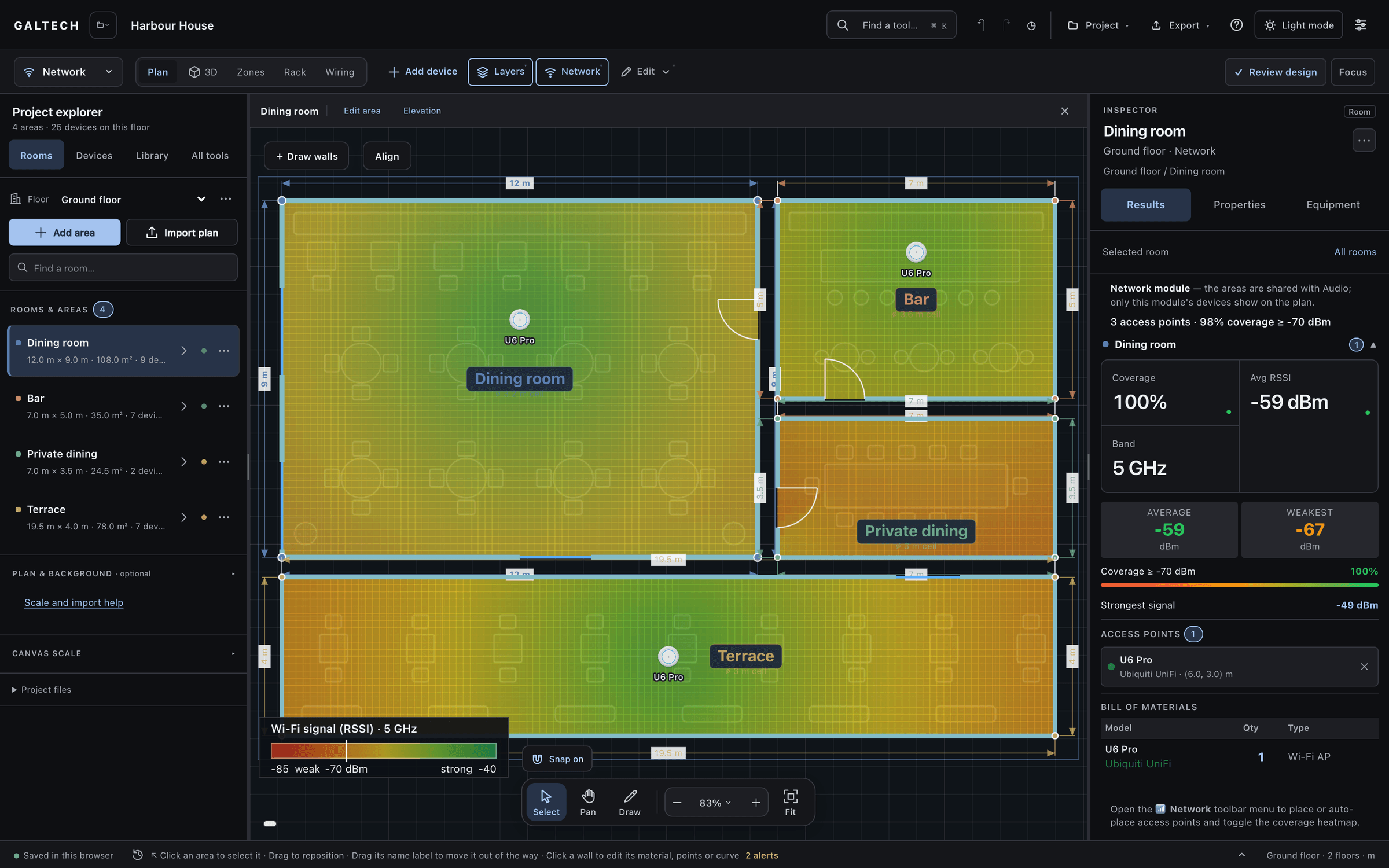
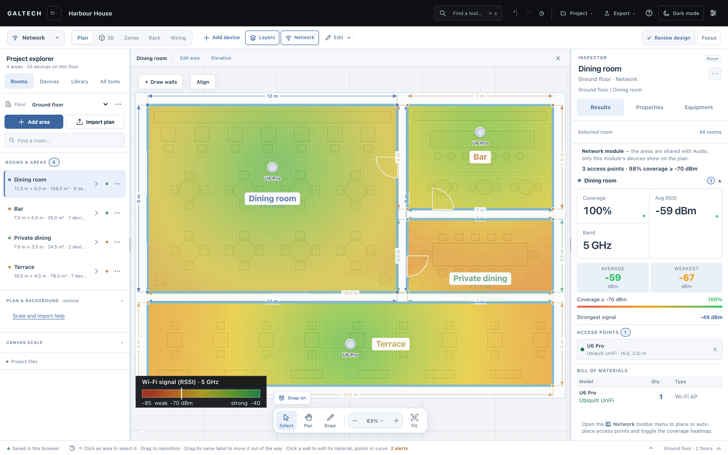
Place access points and check the coverage
- Choose an access point. Open the Library and its access points, search by model or family, and open Details to check the radios, the bands and the power draw before you place it.
- Place it. Choose Place and click where it will be mounted. Drag it with Select to move it; the heatmap follows.
- Compare the coverage with the plan. In Layers, turn on Wi-Fi coverage heatmap. Turn it off and on again to relate the coloured regions to the walls, then expand RSSI Scale in the Inspector.
- Check the band and the walls. In Network tools, choose the radio band and check the wall materials.
- Check the wired side. Review the project’s Equipment, the network results and the wiring schematic: every access point needs a switch port and PoE power.
Read the heatmap
The plan colours each room by predicted signal strength, in dBm: green is strong, orange is usable and red is weak. The scale runs from −85 to −40 dBm.
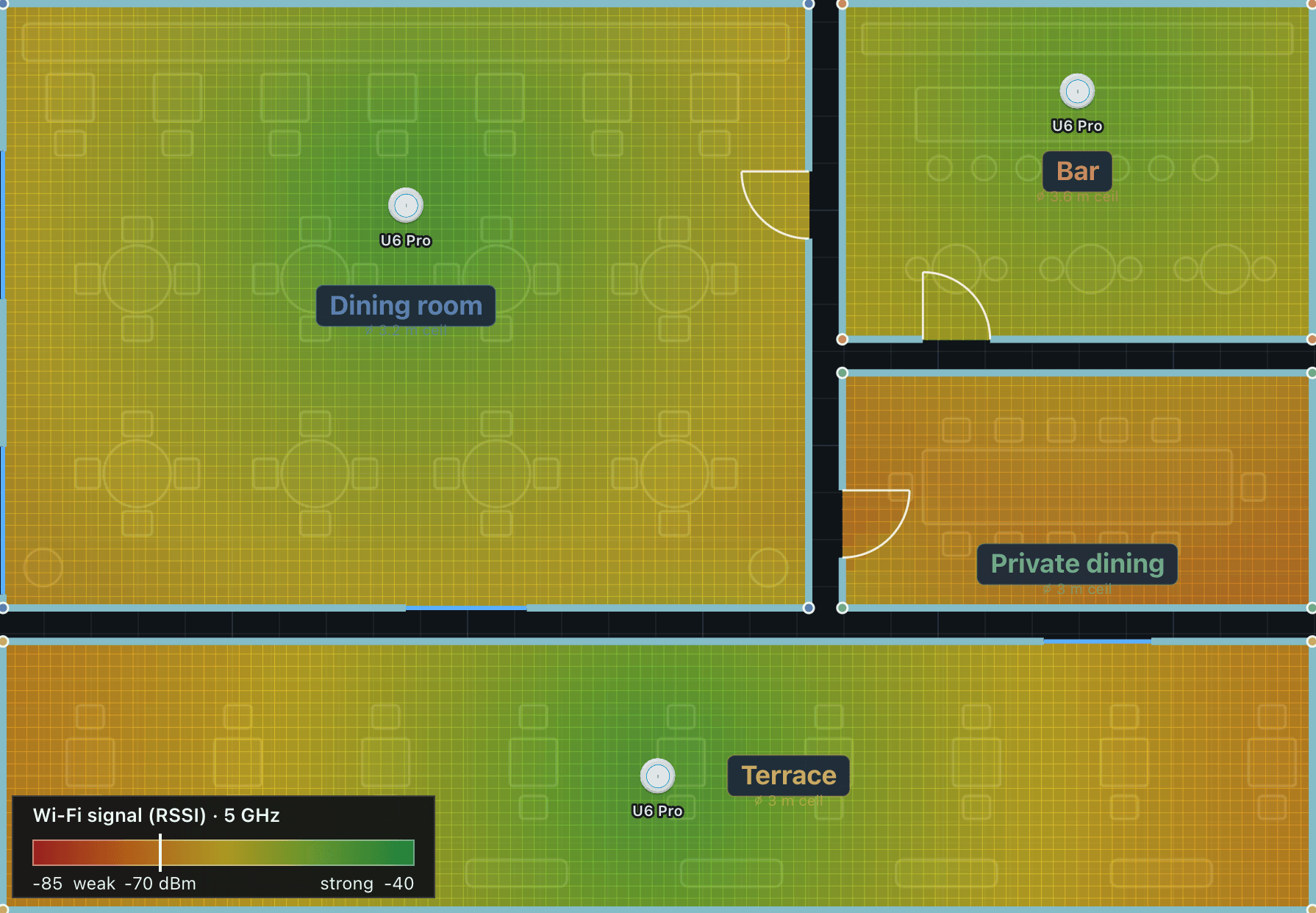
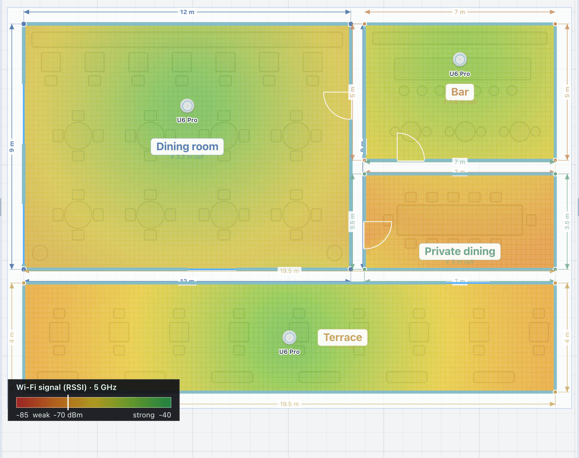
Bands and walls
Check the coverage per band, at 2.4, 5 and 6 GHz, because walls absorb each one differently. Five gigahertz is faster and shorter in range; 2.4 GHz reaches further through walls. A common approach is to plan for 5 GHz and let 2.4 GHz fill the gaps.
The walls matter as much as they do for sound. A glass partition barely touches the signal, and a concrete wall takes a large bite out of it. Set a material for the project or for each wall, and the heatmap reflects it. If you set the wall materials while drawing the rooms, the Wi-Fi design already knows them. The height of a ceiling-mounted access point is part of the calculation too.
The results
For the selected area, the Inspector’s results give the coverage, as the share of the area above the signal threshold, the average signal, the strongest and weakest readings, the access points placed there and a bill of materials for the discipline. If a corner is red, move an access point towards it, or add one, and watch the numbers change. Rooms differ in what they need: a bedroom tolerates less signal than a home office.
Auto-place
Set a target coverage between 80% and 100% in the Network tools and choose Auto-place access points. The tool places just enough access points to reach the target in every area, from the room sizes and the wall materials. Drag any of them afterwards; the heatmap follows.
The wired side
Every networked device in the project needs a switch port: access points, cameras, touch panels, audio players and AV-over-IP video. The tool counts them against the ports your switches provide and warns the moment they run out, so you can add a switch. The Equipment tab is shared across disciplines: check the port count and the PoE budget there before you choose a switch. Its buttons open the rack and the wiring, where the access points already appear.
Your own models
The Network library has two lists: the Wi-Fi access points, each with its photo, bands, gain and PoE draw, and the switches and routers. If a model you install is not there, Import CSV or a custom device adds it with its ports, PoE and rack units, and it joins the rack, the wiring and the bill of materials. Adding your own products is switched on per account for paid subscriptions, on request.
The Wi-Fi report
The network has its own branded report, with the coverage map, the access point schedule with mounting locations and a switch summary. Choose it in Export → Prepare reports, on its own or in the combined report. See Prepare reports and the handover package.
Note
Treat the result as a planning estimate. Validate the radio coverage on site with a survey tool: furniture, people and a different band all change it.