Systems
Plan control and automation
Count the touch panels, door stations and cameras per room, choose what the controller drives, and let the tool size an ELAN processor, its ports and its parts.
On this page
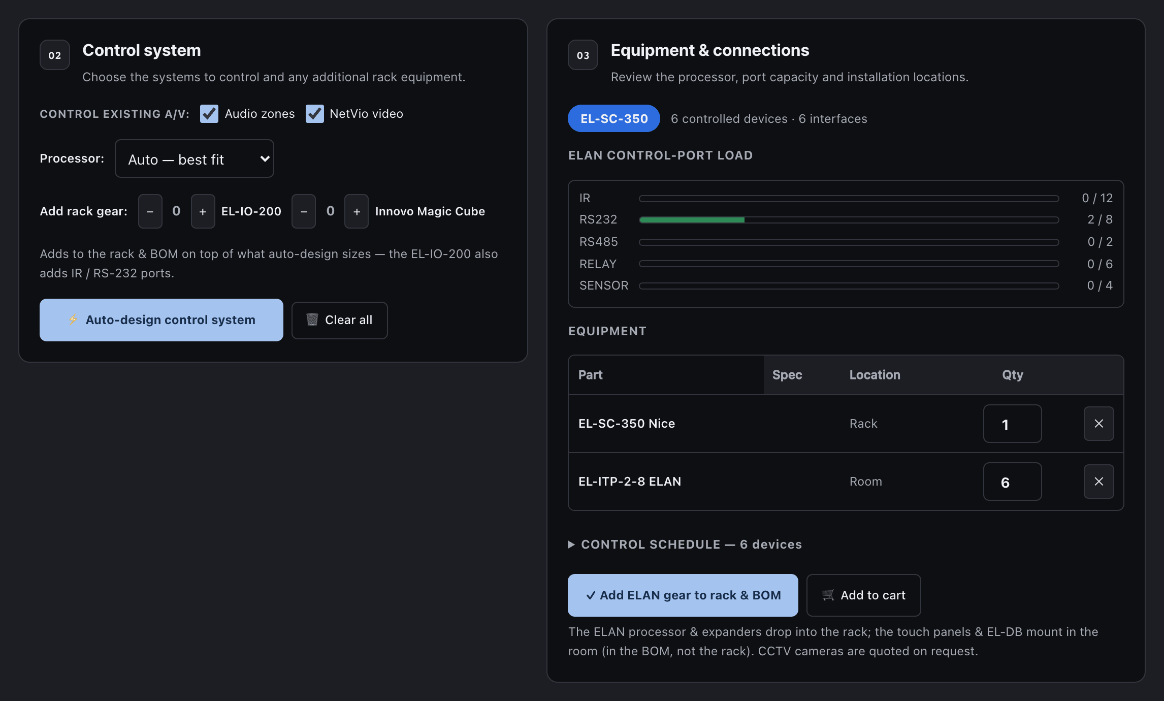
The control system is designed in a dialog, like video. Switch the discipline selector to Automation, then open Library → System design. You count the devices each room needs; the tool sizes an ELAN system for them and for the audio and video it will control, then puts the controller in the rack and its links on the wiring.
Design it
- Count the room devices. For every area, enter the touch panels by size, the video door stations and the cameras. Prefill typical puts one touch panel in each area as a starting point: adjust it for the real installation.
- Choose what it controls. The system step sets what the controller has to drive: the audio zones, Netvio video, lighting, climate and security.
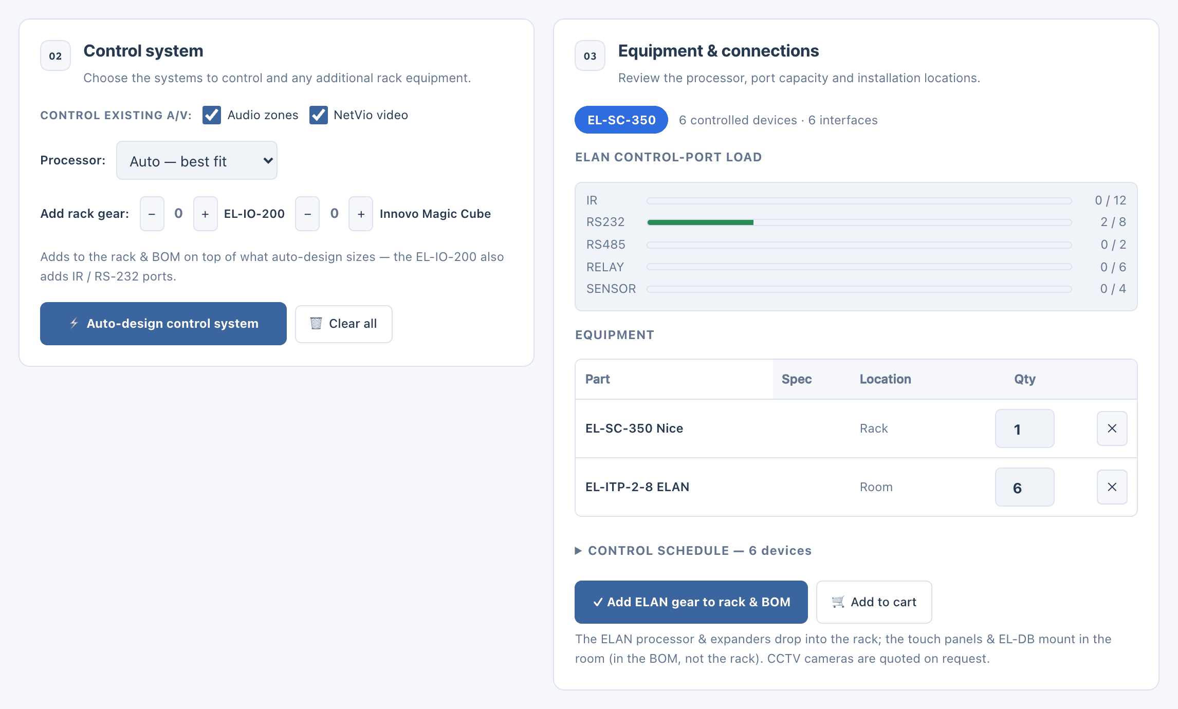
- Auto-design. Choose Auto-design control system. Inspect the controller, its I/O capacity, the user interfaces and the room assignments, and compare them with the connections you need.
- Review the schedule. Close the designer and look at Rack and Wiring. Use the Schematic for individual links, and check the IP, serial, IR and relay connections before you issue the installer’s schedule.
The room devices
The grid takes, per area:
- ELAN touch panels, EL-ITP-2-8 and EL-ITP-2-12,
- Innovo touch screens, TP-4 and TP-5.5,
- EL-DB video door stations,
- and CCTV cameras.
These mount in the rooms and run on the network, powered over PoE. Below the grid, Add rack gear adds EL-IO-200 expanders and Innovo Magic Cube control hubs by hand, on top of what auto-design sizes.
How it sizes the controller
Because the panels, the door station and the cameras are on the network, the controller is sized for the AV integration, over IR and RS-232 on its control ports: an EL-SC-150 for smaller jobs, an EL-SC-350 for larger ones, and EL-IO-200 expanders when the ports overflow. A port-load bar shows the load on each type of port, and warnings flag anything that will not fit, so you know when you need the next controller up or an expander.
What you get
- A control schedule: every device, its area and how it is wired.
- The parts. The processor and expanders go in the rack; the touch panels and door stations mount in the rooms, so they appear in the bill of materials but not in the rack. Cameras are quoted on request.
- The wiring. The single-line diagram draws everything: the door station with its full panel, PoE, door-strike relay and exit button, and the touch screens and cameras wired to the network switch.
- A Control & Automation section in the client proposal, with the full schedule.
Clear all removes the room device counts and the designed ELAN equipment, from the rack, the bill of materials and the wiring as well; the areas stay.
Your own controllers and the report
The controllers library holds the ELAN family, with photos and real rear panels: the EL-SC-150 and EL-SC-350 processors, EL-IO-200 expanders, touch panels, keypads and door stations. Paid accounts can add a custom controller or panel, switched on per account on request, and it flows into the rack, the wiring and the bill of materials. Automation has its own branded report, with the processor, the panels, the control schedule and the equipment: choose it in Export → Prepare reports.
Note
A design schedule records the intended hardware and connections. Programming the system and checking it on site are still part of the installation.