Systems
Build the equipment rack
Fill the rack from the project in one step, arrange it by hand, check the front and the rear with its PDUs, and read the power, heat and weight before export.
On this page
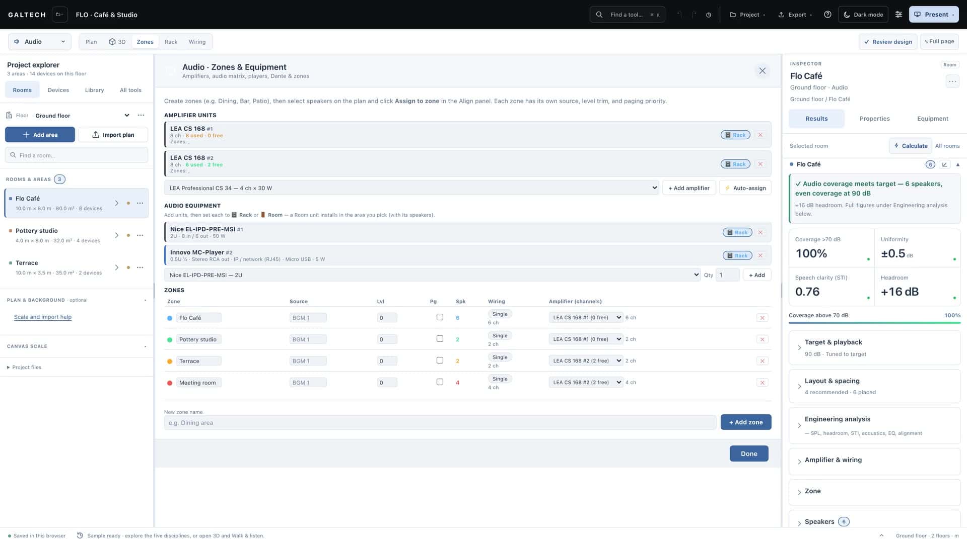
The Rack view is the equipment rack the installer will build. It uses the same project equipment as Zones and Wiring, across every discipline, so an amplifier you add in Zones is already waiting on the left.
Build the rack
- Check where things are installed. Open Zones and separate the room equipment from the shared rack equipment. A player behind the bar belongs to a room, not to the rack.
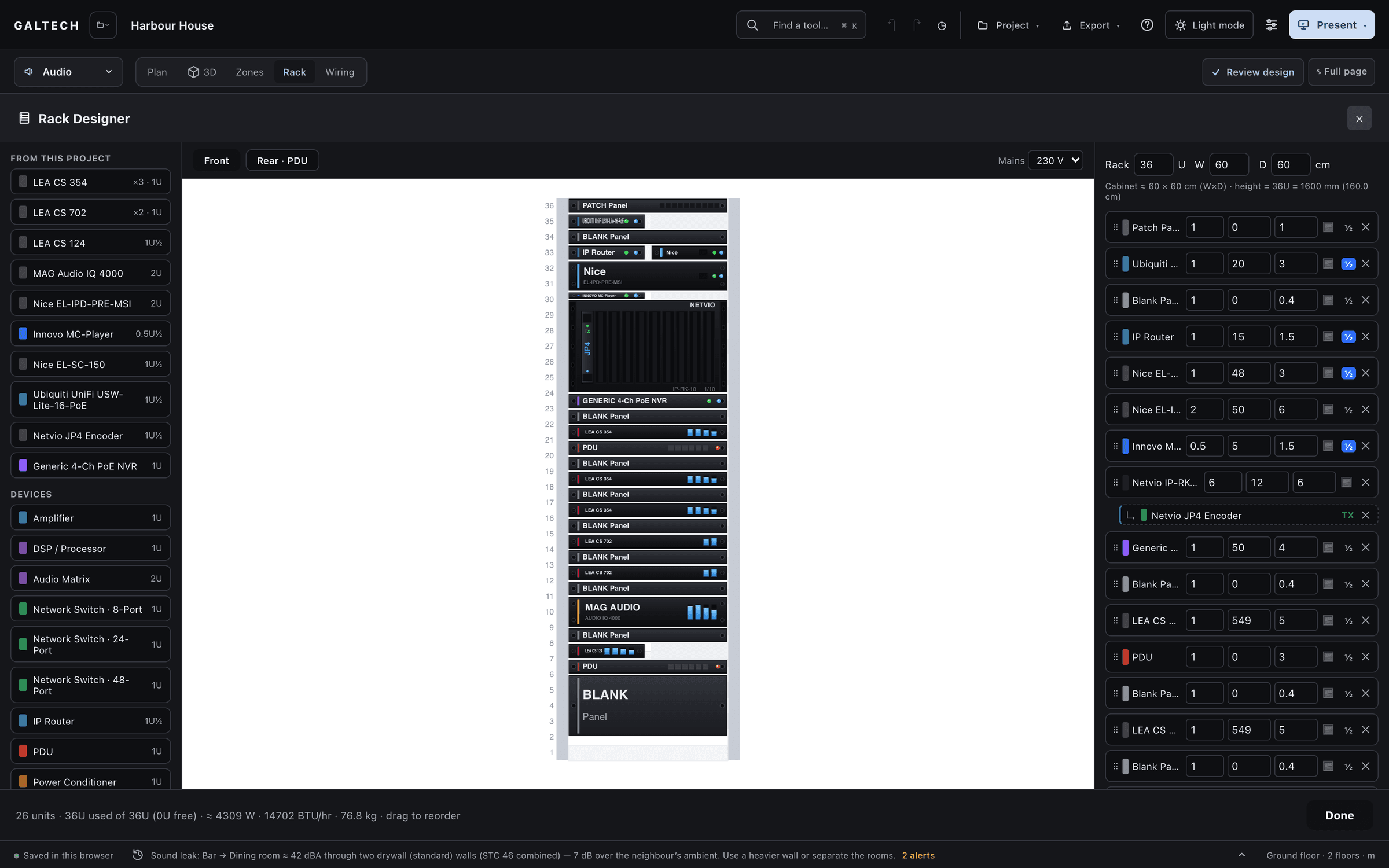
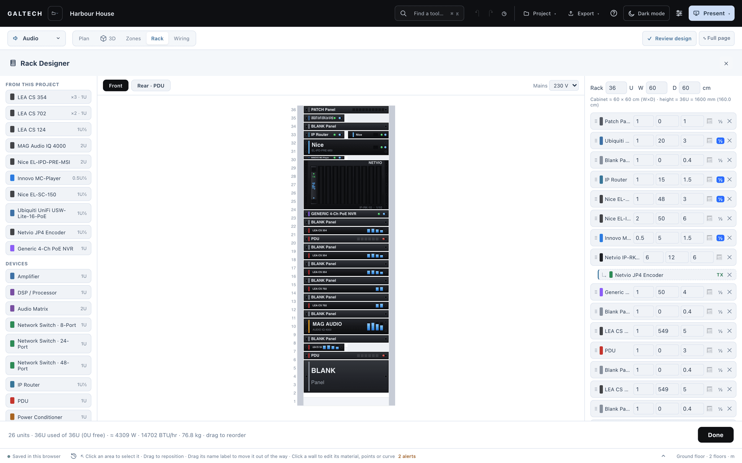
- Fill it. Open Rack and choose Auto-fill from project. The tool lays out every rack device from the current equipment and resizes the cabinet to fit.
- Check the front and the rear. Review the occupied units and the cabinet’s width and depth. Switch to Rear · PDU to check the patching and the power, then return to Front.
- Check the details. Compare the physical sizes, the available ports and the power capacity with the equipment’s specifications before you use the drawing for installation.
How auto-fill lays it out
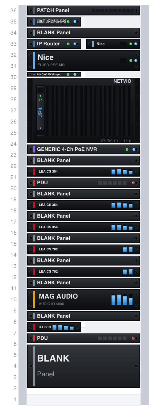
Auto-fill works top to bottom, in the order an installer would choose:
- Patch panels, one per 24 ports of the switch,
- the network switch, and a separate Netvio switch for the AV-over-IP equipment if there is one,
- a 1U blank,
- the ELAN controllers,
- the IP router, at half width,
- the rest of your equipment,
- the amplifiers at the bottom, with a 1U blank before each row; half-width amplifiers pair side by side,
- PDUs sized to the mains-powered equipment, six outlets each,
- and a 4U blank.
If you build by hand, drop the devices in any order, then choose Organise rack to apply the same rules.
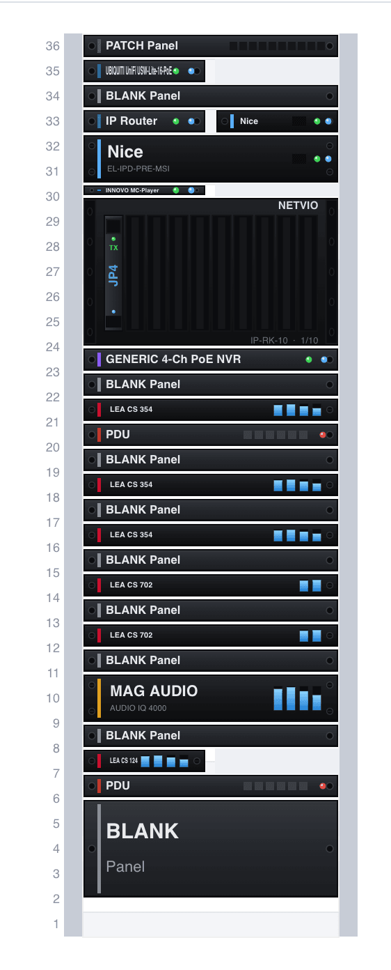
Arrange it by hand
- Add devices from the palette: the project’s amplifiers and equipment, or generic units such as an amplifier, DSP, audio matrix, network switch, power conditioner, UPS, PDU, patch panel, shelf, drawer, vent, blank panels or a custom device. A network switch brings its patch panels with it, one per 24 ports.
- Reorder by dragging, in the list or on the rack. Set each unit’s height in rack units, and toggle ½ for half width.
- Size the cabinet in units, with its width and depth in centimetres, 60 × 60 by default. The height follows the unit count, at 44.45 mm per unit.
- AV over IP. The Netvio section adds an empty 6U card cage; slot encoders and decoders into its bays one at a time. They are powered over the network, so they do not count against the PDUs.
Clear rack takes every unit out and resets the cabinet to 24U, 60 × 60 cm. The equipment stays in the project, so Auto-fill from project builds it again.
The rear and the power
Drop a PDU into the rack and switch to Rear · PDU: each powered unit’s cable is routed through a cable manager to a PDU socket, six per PDU. A cable and port schedule lists every unit’s position, its signal connections, its PDU outlet and its watts. It is the page the installer patches the rack from.
Set the mains voltage, 230 V or 120 V, and the power budget sizes the installation: the total power draw, the current with 25% headroom, the recommended breaker, the number of PDUs, the heat in BTU/h and the weight. Each unit’s power and weight can be edited.
Faceplates and photos
Every unit gets a branded faceplate drawn for it, so the elevation reads like the real rack. To show the real front panel, click a unit and add your own photo; click the thumbnail to remove it again.
A port warning, from every discipline
As you design in any discipline, the tool counts every networked device that needs a switch port, such as access points, cameras, door stations, touch panels, Dante adapters, audio players and AV-over-IP video, against the ports your switches provide. When a device you add would exceed them, a warning tells you to add another switch, and clears once you do.
Export it
Export the rack from the designer as a PDF, with the front, the rear, the cable schedule and the power budget, as a real-scale DXF that opens in AutoCAD, BricsCAD, LibreCAD or SketchUp, or as a PNG. The rack also appears in the main report, and it is saved with the project.