Systems
Read and export the wiring
Follow every port and cable ID from the system diagram to the schematic and room sheets, wire and route by hand where needed, and export drawings and schedules.
On this page
The Wiring view is the connection drawing for the whole project: audio, network, cameras, video and control on one sheet. It is built from the design, every cable gets an ID, and the same IDs print on the schedules, the room sheets and the report, so the installer can label both ends before a cable goes into the wall.
Three views of the same wiring
| View | What it shows | Who it is for |
|---|---|---|
| Schematic | Port-level connections, with each device’s real rear connectors | The installer and the commissioning engineer |
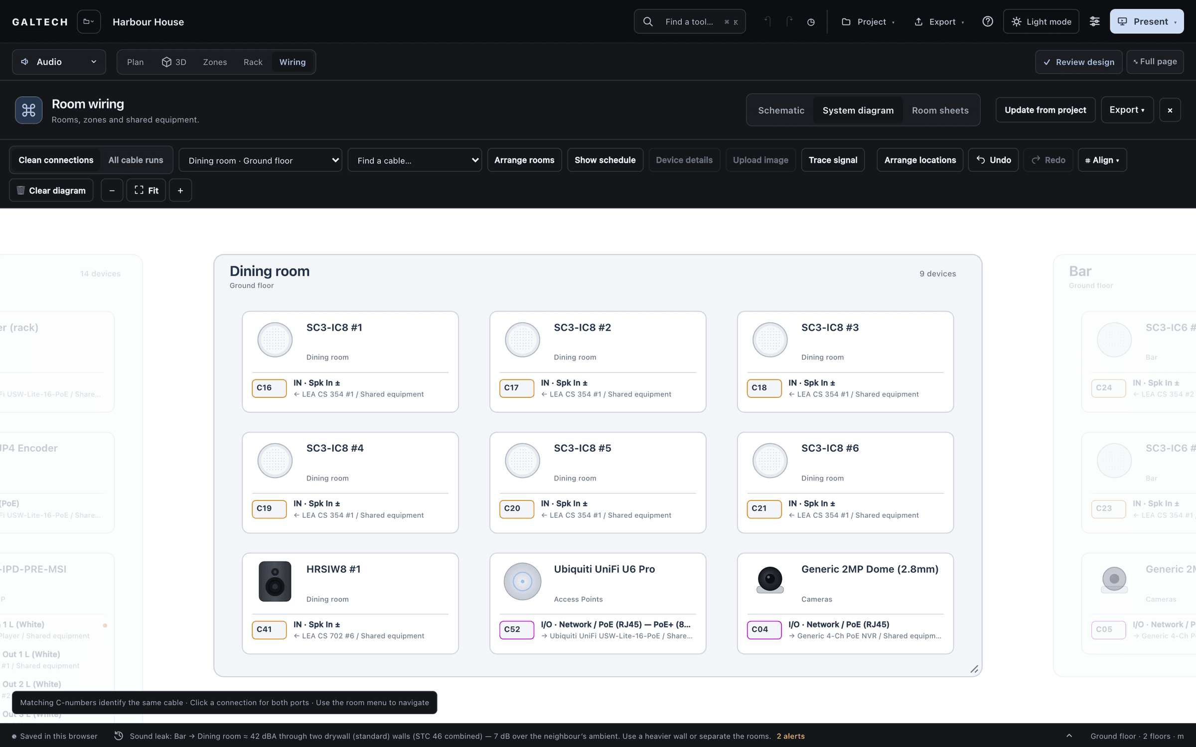
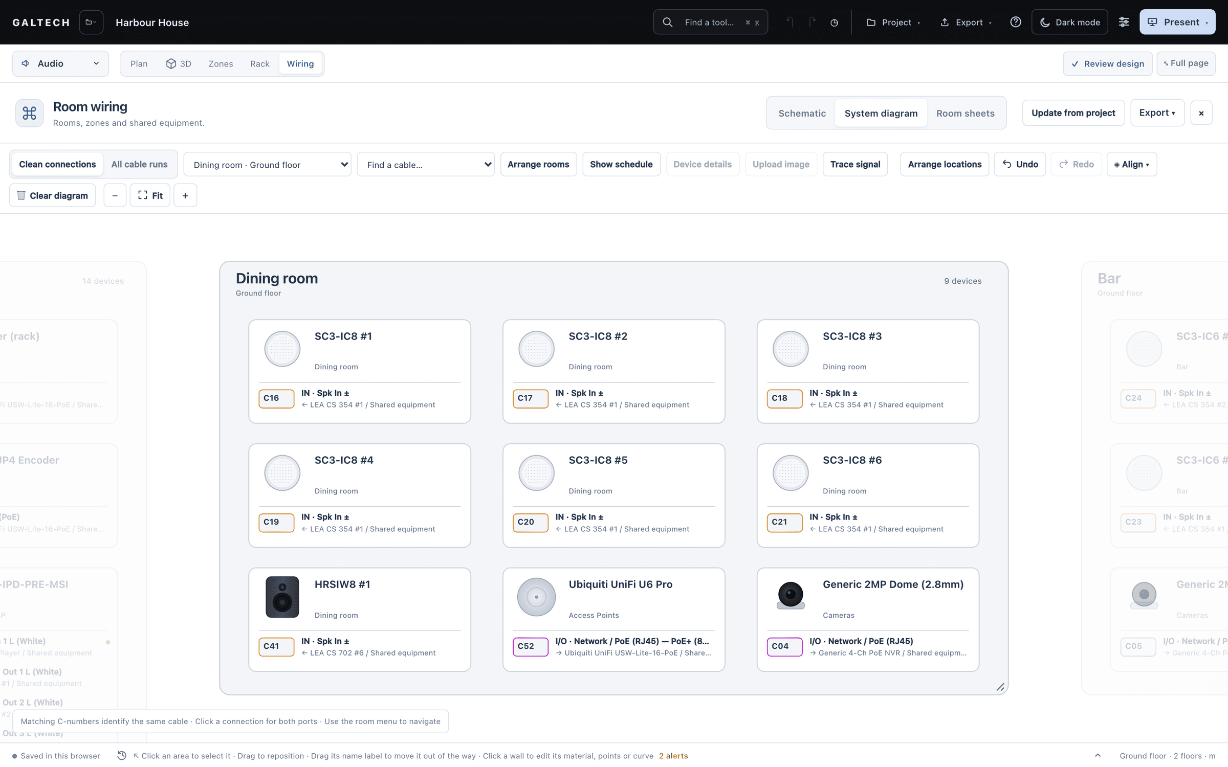
| System diagram | The broader relationships between devices, with product photos, grouped by location | The client, in the proposal |
| Room sheets | The installation grouped by location: one section per room, plus one for the shared rack | The crew working in each room |
Read the drawing and the schedule together
- Open Wiring above the canvas and choose the view you need.
- In Schematic, choose Arrange locations, then use the zoom controls to follow the connections.
- Choose Show schedule. The cable list appears beside the drawing: each cable’s ID, its source device and port, its destination device and port, and its type.
- Open Export and choose the format you need. For CAD, Export CAD downloads the wiring DXF; keep it with the cable schedule.
Built from the project
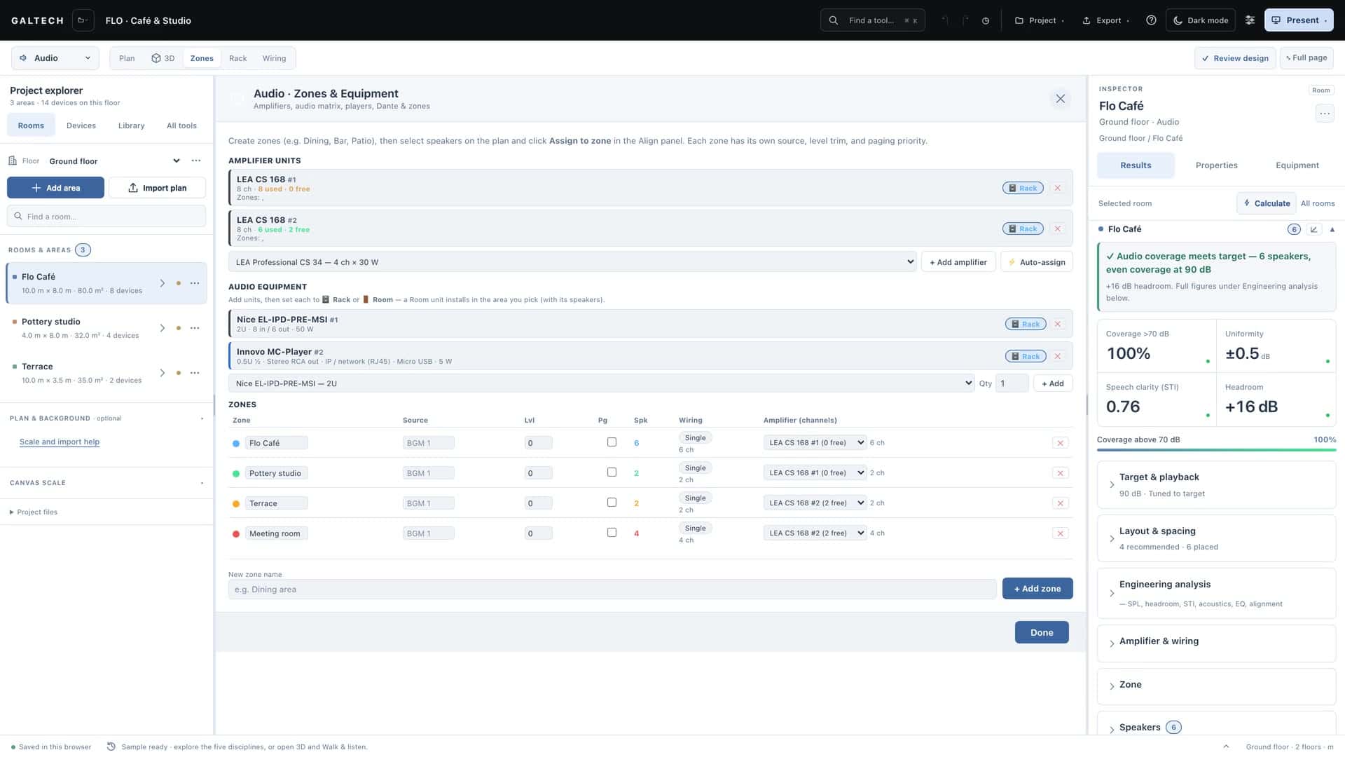
Build from project draws every device in the design: amplifiers, the audio matrix and DSP, switches, controllers, AV-over-IP encoders and decoders, matrices, every placed speaker, and the access points and cameras, each wired to the network switch over PoE. It also includes anything you placed by hand in the rack. On the first build it wires the obvious signal chain for you: sources to the matrix, the matrix to the amplifiers, each amplifier to the speakers in its zones, and 70 V or 100 V lines daisy-chained.
Your own blocks, names, positions and wires are kept when you build again, and Update from project redraws the drawing after you change the design.
Real connectors, per model
Each device is drawn with its real rear-panel connectors, taken from the manufacturer’s data. An eight-channel amplifier shows its eight inputs and eight speaker outputs; a control processor shows its IR, RS-232 and relay ports; a video encoder its HDMI, network, audio, USB and control ports.
Cable types and colours
Cables are identified from their connectors and colour-coded, in the legend and the schedule: speaker cable, network, HDMI, and audio as RCA, optical, coaxial or balanced, with IR as its own cable. Cable colours shows the legend.
Wire and route by hand
- Wire. Drag from an output port to a matching input. The tool blocks output to output, input to input and mismatched signals.
- Route. Click a wire to select it, then drag it to add a bend point, and drag any point to route the wire around the blocks. Double-click a point to remove it, or the wire to reset it.
- Remove. A selected wire’s ✕, or Delete.
- Add devices that are not in the design: a source, a display, a microphone, a PDU, or from + Network a switch, an IP router, an IP camera, an access point or a recorder. Rename them, such as “Lounge TV”, with ✎ or a double-click.
- Edit together. Shift-click devices, or hold Shift and drag a box around them, or press CtrlA for all. Drag one to move the group, align them from Align, or resize them from the corner handle; every cable stays plugged in. Undo and redo step through every change.
The system diagram
The system diagram is the client-facing version. Devices are laid out from left to right, from the rack’s sources through processing and the network to the amplifiers, then into the rooms. Each room is its own box, with that room’s receivers, screens, speakers, panels and cameras in a grid, shown with their real product photos and joined by smooth cables coloured by signal. Drag a room’s box to move the whole room, or its corner to resize it. You can set your own photo on any device.
Room sheets
Room sheets group the installation by location, one section per room plus one for the shared equipment in the rack. Each device card shows its connections and the cable IDs. Each room can be exported on its own as a PDF or an image, for a crew that only needs the sheet for the room they are working in. A connection that cannot be resolved is flagged here for review, not silently left off.
Export
| Format | What you get |
|---|---|
| PNG or PDF | The view you are looking at. The PDF has a title block with the project, the date and your branding, splits a large drawing across numbered sheets so the text stays readable, and ends with a numbered connection schedule. |
| Wiring DXF | The devices, the routes and a cable legend, on their own layers. |
| Room sheets | One sheet per room, as a PDF or an image. |
The wiring DXF is a different export from the floor plan DXF: send each to the person who needs it. See Export CAD drawings.
Tip
Run Review design before you export. It catches connections with a missing port and takes you straight to the wiring to fix them.