On this page
There are two ways to connect a speaker to an amplifier, and the choice shapes the cable, the amplifier, the sound and the rack. This article sets out how each works, where each fits, and the arithmetic worth checking before you commit.
Low impedance
In a low-impedance system the speaker connects straight to an amplifier channel. Its nominal impedance, usually 4 Ω or 8 Ω, is the load the amplifier sees, and an amplifier’s rated power is always quoted into a stated load.
Speakers wired in parallel lower that load:
Two 8 Ω speakers in parallel make 4 Ω; four make 2 Ω. Every amplifier has a minimum load it is rated to drive, and going below it risks overheating, protection shutdowns or damage. Series-parallel wiring brings the load back up: four 8 Ω speakers wired as two series pairs, with the pairs in parallel, present 8 Ω.
Low impedance is sensitive to cable resistance, because the cable sits in series with a small load. The tool sizes the cable so that the round-trip resistance stays within 7% of the channel’s impedance for residential background music, which lets 16 AWG cover typical runs of about 21 m at 8 Ω. For professional runs, and for any subwoofer, it keeps within 5% with 12 to 8 AWG.
Low impedance usually fits:
- a few speakers per channel, not far from the rack;
- music where full bandwidth matters, with no transformer in the way;
- subwoofers, always on channels of their own;
- homes, home cinemas and bars.
70 V and 100 V lines
A constant-voltage line works the other way round. At full power the amplifier’s output reaches 70 V or 100 V. Each speaker has a step-down transformer with taps, for example 30 W, 15 W, 7.5 W and 3.75 W, and the tap you choose sets that speaker’s share of the power and so its level. The speakers simply hang off the line in parallel.
The rule is to add up the taps. Their total on a channel must stay below the channel’s rated power, with a margin: the tool loads a line channel to no more than 80% of its rating. A 240 W channel on a 100 V line can therefore carry about 192 W of taps: twelve speakers on 15 W taps, or twenty-five on 7.5 W.
Each tap presents an impedance of V² ÷ P, so a 15 W tap on a 100 V line is about 667 Ω, and a long chain of speakers is still an easy load. Because the current is low, long runs need far lighter cable than low impedance would; the tool sizes line cable to keep the voltage drop within 10%.
The costs are real, though:
- Transformers lose a little level and limit the low bass. Driven hard at low frequencies they saturate, so a high-pass filter on the line channel protects them.
- A tap is a ceiling. A speaker can never draw more than its tap, which caps its level and its headroom.
- The voltage is regional. 70 V is usual in North America; 100 V lines are widespread in Europe, the Middle East and much of Asia. Match the amplifier’s line output to the speakers’ transformers.
Lines usually fit:
- many speakers across a large floor: shops, offices, hotel corridors, car parks;
- long runs to gardens and outbuildings;
- paging and background music over many zones;
- jobs where a speaker may be added later without rewiring.
Mixing the two
Many jobs use both. Ceiling speakers ride a 100 V line across a shop floor while the subwoofer sits on its own low-impedance channel. Dual-voltage models, such as the Nice SC-OG-4 and SC-OG-6 landscape satellites, can be wired either way.
In the tool each area has a Low impedance, 70 V or 100 V setting under Amplifier & wiring. On a line, every main speaker rides it and any subwoofer stays on its own 8 Ω channel automatically. You can override the connection for a single speaker in its properties, and a mixed zone, line satellites with a low-impedance subwoofer, is sized correctly on both sides.
Channels and zones
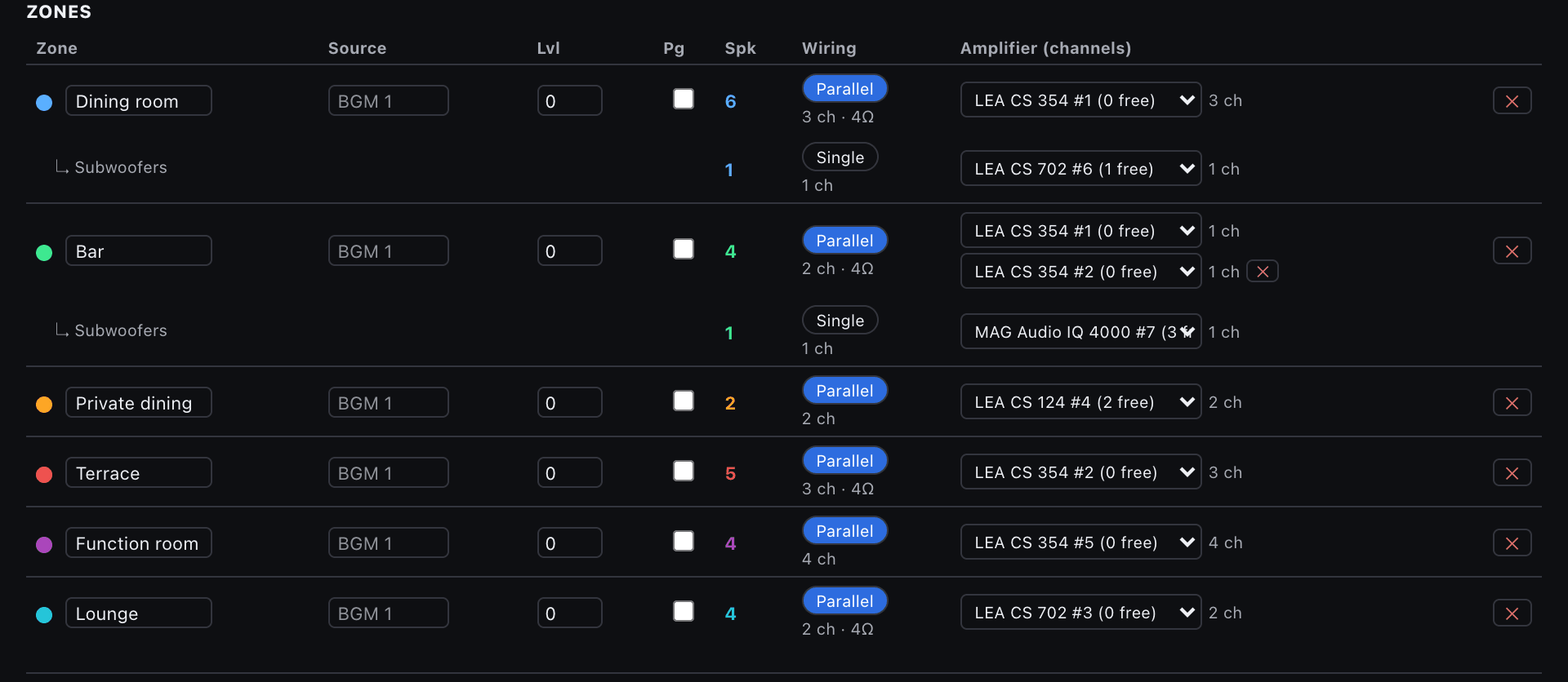
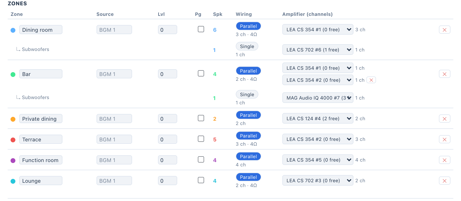
Every area starts as its own zone, and a zone takes channels on an amplifier, either Single, one channel per speaker, or Parallel, two 8 Ω speakers on each 4 Ω channel. Four speakers need four channels single, or two in parallel.
When a zone has more speakers than its amplifier has channels, it spans a second unit, and until it has one the heatmap shows the speaker left without power. The level the heatmap predicts follows the amplifier you assign: an underpowered channel lowers it, so a shortfall shows on the plan rather than on site.
Power and heat
Amplifiers never deliver their full rating continuously on real programme material, and sizing the mains and the cooling for nameplate power wastes both. The usual design figures are:
- typical programme: one eighth of rated output;
- heavy, sustained programme: one third of rated output.
What the rack has to get rid of is the difference between what an amplifier draws from the mains and what it sends to the speakers. To turn watts of heat into BTU per hour, multiply by 3.412.
The tool works this out for every amplifier in the project at both levels, using the datasheet’s power consumption where it has one and a Class D efficiency of about 85% where it does not. The Rack Designer adds the rest of the equipment and gives the total draw, the current with 25% headroom, a recommended breaker, the number of PDUs and the heat in BTU per hour, for 230 V or 120 V mains.
Before you commit
- Confirm each amplifier’s minimum load, and whether it has line outputs.
- Count channels per zone, single or parallel, and keep the subwoofers separate.
- On lines, add up the taps and keep the margin.
- Size the cable for the run, not out of habit.
- Put the high-pass filters, levels and limiters on the DSP preset sheet the installer will load.